Collaborative robot
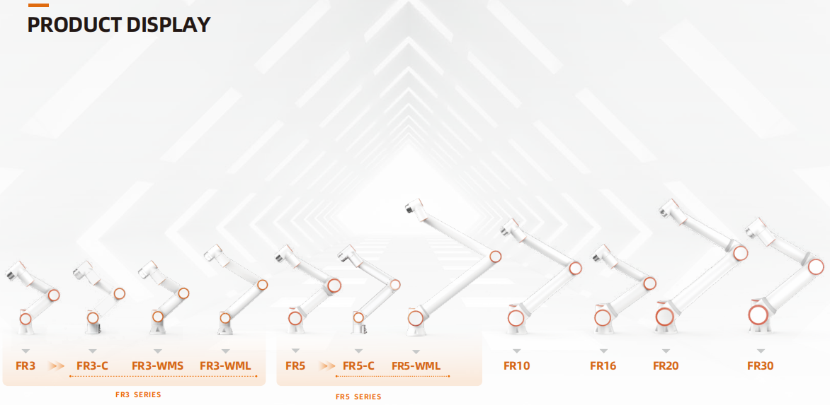
Product matrix
Quick start
Manual
- 1. Foreword
- 2. Robot brief introduction
- 3. Installation
- 3.1. Instructions for security
- 3.2. Equipment transportation
- 3.3. Maintenance, inspection, and scrapping
- 3.3.1. Maintenance disposal
- 3.3.2. Inspection Plan
- 3.3.3. Digital Input/Output Description of Control Box
- 3.3.4. Robot waste disposal
- 3.4. Installation specifications
- 3.4.1. Robot arm installation
- 3.4.2. Tool end installation
- 3.4.3. Installation environment
- 3.4.4. Floor carrier capacity
- 3.4.5. Load curves for all FR series models
- 3.4.5.1. Overview
- 3.4.5.2. Parameter Description
- 3.4.5.2.1. FR3 Model Collaborative Robot Load Curve
- 3.4.5.2.2. FR3-WMS Model Collaborative Robot Load Curve
- 3.4.5.2.3. FR3-WML Model Collaborative Robot Load Curve
- 3.4.5.2.4. FR3-C Model Collaborative Robot Load Curve
- 3.4.5.2.5. FR5 Model Collaborative Robot Load Curve
- 3.4.5.2.6. FR5-WML Model Collaborative Robot Payload Curve
- 3.4.5.2.7. FR5-C Model Collaborative Robot Load Curve
- 3.4.5.2.8. FR10 Model Collaborative Robot Load Curve
- 3.4.5.2.9. FR16 Model Collaborative Robot Load Curve
- 3.4.5.2.10. FR20 Model Collaborative Robot Load Curve
- 3.4.5.2.11. FR30 Model Collaborative Robot Load Curve
- 3.5. Control connection
- 3.5.1. Controller interface
- 3.5.2. Controller I/O panel
- 3.5.3. RJ45 network interface group
- 3.5.4. End plate
- 3.5.5. Ground
- 3.5.6. The common specifications of all digital I/O
- 3.5.7. Safety I/O
- 3.5.8. Universal digital amount I/O
- 3.5.9. Digital input from the button
- 3.5.10. Interact with other devices or PLC
- 3.5.11. Simulation I/O
- 3.5.12. FR3MT&3C Optional Modules
- 3.6. Demonstrate and end LED
- 4. Quick start
- 5. Teaching pendant software
- 6. Base
- 6.1. Installation
- 6.2. Coordinate
- 6.3. Payload
- 6.4. Joint
- 6.4.1. Soft limit
- 6.4.2. Collision level
- 6.4.3. Friction compensation
- 6.4.4. Friction Compensation Coefficient Adjustment Function
- 6.4.5. Dragging Force Compensation
- 6.5. I/O setup
- 6.6. Joint origin
- 6.7. Photoelectric Sensor TCP Auto-Calibration Function
- 6.8. TCP Calibration based on flatbed
- 6.9. Control Box Analog Feedback Arc Tracking Function
- 6.10. Linear Rack Guideway Collision Detection
- 6.11. Force Sensor Loaded Zeroing and Open Posture Compliance Admittance Parameters
- 7. Safety
- 7.1. Stop mode
- 7.2. Safe speed
- 7.3. I/O safety
- 7.4. Emergency stop
- 7.5. Protective stop
- 7.6. Interference zone configuration
- 7.7. Reduction Mode
- 7.8. Safety plane
- 7.9. Daemon
- 7.10. Direction limit (Only used in Linux systems)
- 7.11. Robot limit (Only used in Linux systems)
- 7.12. Power detection (Only used in QX systems)
- 7.13. Motion Configuration
- 8. Peripherals
- 8.1. End-Effector Lua Custom Open Protocol
- 8.2. Gripper
- 8.3. Force Sensor
- 8.3.1. Pre-Adapted Devices
- 8.3.2. Force Sensor End-Effector Lua Protocol
- 8.3.3. Welding Handle End Lua Protocol
- 8.3.4. Sensor Load Identification
- 8.3.5. Force Sensor Assisted Dragging
- 8.3.6. Force/Torque Sensor Collision Detection
- 8.3.7. Force/Torque Sensor Force Control Motion
- 8.3.8. Force/Torque Sensor Spiral Insertion
- 8.3.9. Force/Torque Sensor Rotation Insertion
- 8.3.10. Force/Torque Sensor Linear Insertion
- 8.3.11. Force/Torque Sensor Surface Finding
- 8.3.12. Force/Torque Sensor Center Finding
- 8.3.13. Custom Open Protocol
- 8.4. Welding Pendant
- 8.5. Spray Gun
- 8.6. Welding Machine
- 8.6.1. Welding Torch Installation
- 8.6.2. Welding Machine Parameter Configuration
- 8.6.3. Welding Program Writing
- 8.6.4. Welding Interruption and Recovery
- 8.6.5. Attachment 1: Robot UDP Communication Protocol
- 8.6.6. Digital Communication Protocol (Modbus TCP)
- 8.7. Extended Axis Configuration
- 8.7.1. Extended Axis Coordinate System
- 8.7.2. Controller + PLC (UDP Communication)
- 8.7.3. Two-DOF Trolley Test
- 8.7.4. Controller + Servo Drive (485 Communication)
- 8.8. Line Laser Sensor
- 8.8.1. Hardware Connection
- 8.8.2. Sensor Configuration
- 8.8.3. Sensor Calibration
- 8.8.4. Laser Sensor Application
- 8.8.5. Laser Sensor Adaptation Controller Peripheral Open Protocol
- 8.9. Polishing
- 8.10. Auxiliary Sensors
- 8.11. Combined Devices (SmartTool + Force Sensor Combination)
- 8.12. Array Suction Cups
- 8.13. CNC Function Package Based on FOCAS (For Linux Systems Only)
- 8.14. Virtual Wall Configuration Based on Force Sensor
- 8.15. Extended Axis with Laser Point Tracking Function
- 8.15.1. Robot Extended Axis with Laser Point Tracking System Composition
- 8.15.2. Extended Axis Communication Configuration
- 8.15.3. Weld Seam Tracking Laser Sensor Connection Configuration
- 8.15.4. Welder Connection Configuration
- 8.15.5. Tool Coordinate System and Laser Sensor Coordinate System Calibration
- 8.15.6. Extended Axis and Laser Point Tracking Function
- 8.16. Laser Seam Finding Point Position Acquisition Function
- 8.17. DARU DFC Force Control Polishing Head Application
- 8.18. End-Effector Transparent Transmission Function
- 9. Coding
- 9.1. Introduction
- 9.2. Tool bar
- 9.3. Program command
- 9.4. Logic Command Interface
- 9.5. Motion command interface
- 9.5.1. PTP command
- 9.5.2. Lin command
- 9.5.3. Arc command
- 9.5.4. Circle command
- 9.5.5. Spiral command
- 9.5.6. N-Spiral command
- 9.5.7. H-Spiral command
- 9.5.8. Spline command
- 9.5.9. N-Spline command
- 9.5.10. Weave command
- 9.5.11. TPD command
- 9.5.12. Offset command
- 9.5.13. Servo Command
- 9.5.14. Trajctory command
- 9.5.15. TrajctoryJ command
- 9.5.16. DMP command
- 9.5.17. WPTrsf command
- 9.5.18. Tool conversion command
- 9.6. Control command interface
- 9.7. Peripheral Command Interface
- 9.8. Welding command interface
- 9.9. Force control command interface
- 9.10. Visual command interface
- 9.11. Palletizing command interface
- 9.12. Communication command interface
- 9.13. Auxiliary command interface
- 9.14. Teaching program is not saved for verification
- 9.15. Teaching program encryption
- 9.16. Local teaching point
- 9.17. Current program backup
- 9.18. Modbus TCP Communication
- 9.19. Robot Backgrounder Function
- 9.20. XY horizontal constant
- 9.21. Automatic Singularity Avoidance Trajectory
- 9.22. Singularity crossing function in automatic mode
- 9.23. Real-time forward trajectory planning function
- 9.24. Swing amplitude monotonous gradual arc tracking function
- 9.25. Offset arc tracking function
- 9.26. Custom collision detection threshold function
- 9.26.1. Overview
- 9.26.2. Function setting description
- 9.27. T-Shape Velocity Characteristic Optimization + Blending Smoothing Function
- 9.27.1. Overview
- 9.27.2. Operation Procedures
- 9.27.2.1. PTP-PTP Blending
- 9.27.2.2. PTP-LIN Blending
- 9.27.2.3. PTP-ARC Blending
- 9.27.2.4. PTP-CIRCLE Blending
- 9.27.2.5. LIN-PTP Blending
- 9.27.2.6. LIN-LIN Blending
- 9.27.2.7. LIN-ARC Blending
- 9.27.2.8. LIN-CIRCLE Blending
- 9.27.2.9. ARC-PTP Blending
- 9.27.2.10. ARC-LIN Blending
- 9.27.2.11. ARC-ARC Blending
- 9.27.2.12. ARC-CIRCLE Blending
- 9.27.2.13. CIRCLE-PTP Blending
- 9.27.2.14. CIRCLE-LIN Blending
- 9.27.2.15. CIRCLE-ARC Blending
- 9.27.2.16. CIRCLE-CIRCLE Blending
- 9.27.2.17. Blending for Extended Axis Asynchronous Motion
- 9.27.2.18. Blending for Extended Axis Synchronous Motion
- 9.28. Swing Tilt Angle Function
- 9.29. Welding process parameter gradient function (current, voltage, travel speed along weld seam)
- 9.30. Robot ModbusRTU Communication
- 9.30.1. Overview
- 9.30.2. Robot ModbusRTU Master Operation Instructions
- 9.30.3. Robot ModbusRTU Slave Operation Instructions
- 9.30.3.1. ModbusRTU Slave Communication Parameter Configuration
- 9.30.3.2. ModbusRTU Slave Communication Test
- 9.30.3.3. Writing a ModbusRTU Slave Program
- 9.30.3.3.1. Write Single Digital Output DO (Discrete Input)
- 9.30.3.3.2. Write Multiple Digital Outputs DO (Discrete Inputs)
- 9.30.3.3.3. Read Single Digital Output DO (Discrete Input)
- 9.30.3.3.4. Read Multiple Digital Outputs DO (Discrete Inputs)
- 9.30.3.3.5. Read Digital Input DI (Coils)
- 9.30.3.3.6. Read/Write Operations for Analog Output AO (Input Registers) and Analog Input AI (Holding Registers)
- 9.30.3.3.7. Wait for Digital Input
- 9.30.3.3.8. Wait for Analog Input
- 9.30.3.4. Robot Status Feedback and Control via ModbusRTU Slave
- 9.31. Protection Based on 6-Axis Force Sensor Posture Compliance Function
- 9.32. Socket Communication Interface Function
- 9.33. Impedance Control Function During Robot Motion
- 9.34. Custom Weaving Welding Function
- 9.35. Teach point configuration
- 9.36. Main program configuration
- 9.37. Robot Extended Axis Intersecting Line Welding
- 10. Graphical programming
- 10.1. Introduction
- 10.2. Logic Graphical Programming Commands
- 10.3. Variable class graphical programming command
- 10.4. Function class graphical programming command
- 10.5. Motion graphic programming commands
- 10.5.1. Point-to-point instruction
- 10.5.2. Straight line instruction
- 10.5.3. Straight line (adjustable angular velocity at transition point) instruction
- 10.5.4. Straight line (seamPos) command
- 10.5.5. Arc command
- 10.5.6. Full circle command
- 10.5.7. Spiral instruction
- 10.5.8. New spiral instruction
- 10.5.9. Horizontal spiral instruction
- 10.5.10. Spline instruction
- 10.5.11. New spline instruction
- 10.5.12. Swing Instruction
- 10.5.13. Point offset instruction
- 10.5.14. Servo command
- 10.5.15. Trajectory command
- 10.5.16. TrajectoryJ command
- 10.5.17. Track reproduction command
- 10.5.18. DMP Command
- 10.5.19. Tool conversion instruction
- 10.5.20. Workpiece conversion instruction
- 10.6. Control class graphical programming commands
- 10.7. Peripheral graphical programming commands
- 10.8. Welding Graphical Programming Commands
- 10.9. Force control graphical programming commands
- 10.10. Communication graphic programming commands
- 10.11. Advanced Graphical Programming Commands
- 10.12. Graphical programming command usage example
- 11. Node graph programming
- 11.1. Basic information
- 11.2. Node graph operations
- 11.3. If/Else instruction
- 11.4. While instruction
- 11.5. Goto instruction
- 11.6. Wait instruction
- 11.7. Pause instruction
- 11.8. Dofile instruction
- 11.9. Set system variable command
- 11.10. PTP instruction
- 11.11. LIN instruction
- 11.12. LIN(seamPos) instruction
- 11.13. ARC instruction
- 11.14. Circle instruction
- 11.15. Spiral instruction
- 11.16. N-Spiral instruction
- 11.17. H-Spiral instruction
- 11.18. Spline instruction
- 11.19. N-Spline instruction
- 11.20. Weave instruction
- 11.21. TPD instruction
- 11.22. Offset instruction
- 11.23. ServoCart instruction
- 11.24. Trajectory instruction
- 11.25. TrajectoryJ instruction
- 11.26. DMP instruction
- 11.27. WPSTrsf instruction
- 11.28. ToolTrst instruction
- 11.29. Digital IO instruction node
- 11.30. Simulate AI commands
- 11.31. Virtual IO command node
- 11.32. Extended IO command node
- 11.33. MoveDO instruction
- 11.34. ToolList instruction
- 11.35. Mode instruction
- 11.36. Collision instruction
- 11.37. Acc instruction
- 11.38. Gripper instruction
- 11.39. Spray instruction
- 11.40. Extended axis instructions (controller + PLC)
- 11.41. Extended axis instructions (controller + servo drive)
- 11.42. Conveyor belt instruction
- 11.43. Polish instruction
- 11.44. Weld command
- 11.45. Segment instruction
- 11.46. Laser instruction
- 11.47. Laser recording instructions
- 11.48. W-Search instruction
- 11.49. Weld-Trc instruction
- 11.50. Attitude adjustment instructions
- 11.51. F/T Instruction
- 11.52. Torque recording command
- 11.53. Modbus instruction
- 11.54. Application scenario usage examples
- 12. Teaching Points
- 13. Status
- 14. Applications
- 14.1. Robot Packing
- 14.2. Data Backup
- 14.3. 10s Data Recording
- 14.4. End-Effector LED
- 14.5. Drag Locking
- 14.5.1. Normal Collision Protection Triggering Under Force Sensor Assisted Dragging
- 14.5.1.1. Overview
- 14.5.1.2. Collision Protection
- 14.5.1.3. Parameters Calibration of Joint Torque Sensor on the Whole Machine
- 14.5.1.4. External Force Estimation and Torque Compensation Based on Momentum Observer
- 14.5.1.5. Assisted Drag Optimization Function Based on Joint Torque Sensor
- 14.5.1. Normal Collision Protection Triggering Under Force Sensor Assisted Dragging
- 14.6. Intersection Point Generation (Laser Point Capture Motion)
- 14.7. Peripheral Protocol
- 14.8. G-code to Robot Trajectory Planning Function
- 15. Process Package
- 15.1. Welding Expert Library
- 15.2. Palletizing System Configuration
- 15.3. Conveyor Tracking
- 15.3.1. Conveyor Tracking Configuration Steps
- 15.3.2. Conveyor Tracking Teaching Program
- 15.3.3. Robot Conveyor Tracking System Composition
- 15.3.3.1. Conveyor Encoder Data Communication Connection Method
- 15.3.3.2. Conveyor Configuration
- 15.3.3.3. Tracking Coordinate System Configuration
- 15.3.3.4. Conveyor Tracking Chase Motion Function
- 15.3.3.5. Conveyor Tracking Chase Motion Function Introduction
- 15.3.3.6. Chase Motion Program Teaching
- 16. System
- 16.1. General settings
- 16.2. Account settings account settings
- 16.3. About
- 16.4. Custom information
- 16.5. Robot model configuration
- 17. Teach pendant
- 18. Custom protocol slave commands
- 18.1. Overview
- 18.2. Industrial Bus Protocol Integration for Robot Motion Control
- 18.3. Environment Configuration
- 18.4. Robot Slave Mode Operation Manual
- 18.5. Board Communication Cycle Configuration
- 18.6. Appendice
- 19. Appendix
- 20. Term
Changelog
- Version V3.9.5
- Version V3.9.4
- Version V3.9.3
- Version V3.9.2
- Version V3.9.1
- Version V3.9.0
- Version V3.8.7
- Version V3.8.6
- Version V3.8.5
- Version V3.8.4.1
- Version V3.8.4
- Version V3.8.3
- Version V3.8.2
- Version V3.8.1
- Version V3.8.0
- Version V3.7.8
- Version V3.7.7
- Version V3.7.6
- Version V3.7.5
- Version V3.7.4
- Version V3.7.3
- Version V3.7.2
- Version V3.7.1