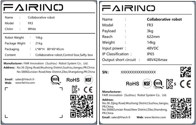
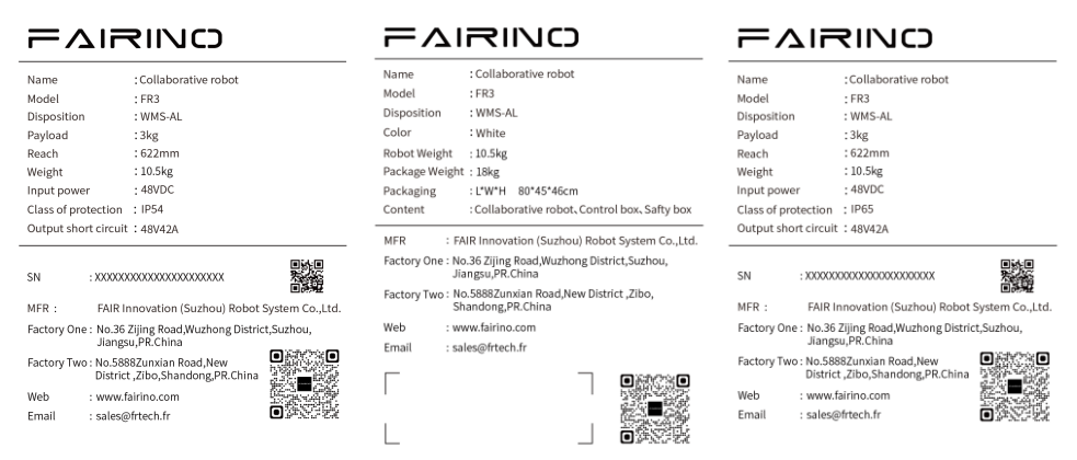
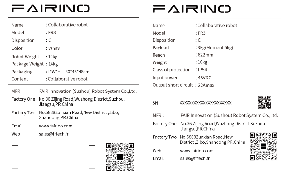
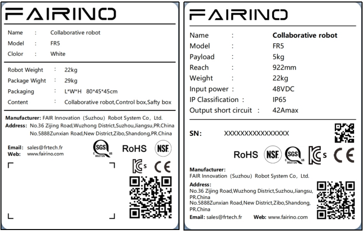
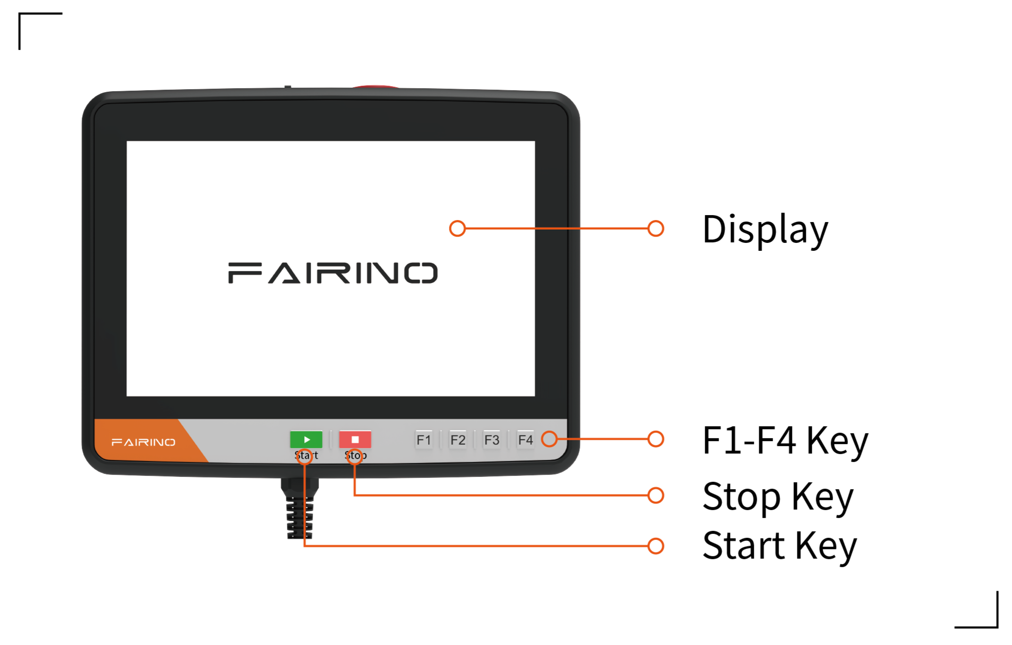
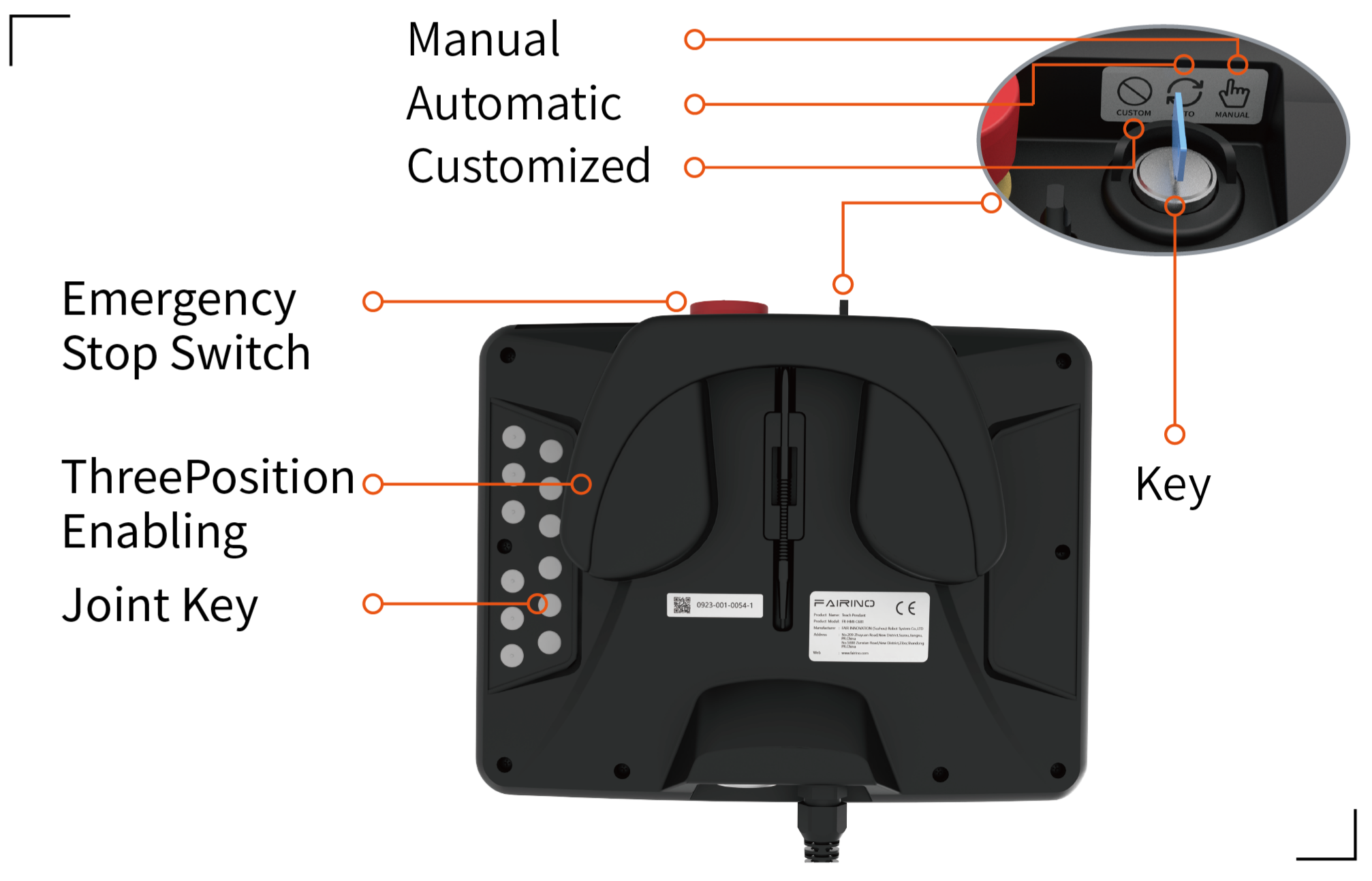
This manual will use the following warnings. The role of these warnings is to ensure the safety of personal and equipment. When you read this manual, you must comply with and execute all the assembly instructions and guidelines in other chapters in this manual. This is very important. Pay special attention to text related to warning signs.
Important
If the robot (robot body, control box, teaching pendant, or button box) is damaged, changed or modified due to anthropogenic causes, FAIR INNOVATION refuses to bear all responsibilities;
FAIR INNOVATION is not responsible for any damage caused by the robot or any other device due to errors written by customers or any other device.
When running the robot system, we must first ensure the safety of the operators. The general precautions are listed below. Please take corresponding measures to ensure the safety of the operator.
All operators who use the robot system should be trained through training courses sponsored by the FAIR INNOVATION (Suzhou) ROBOTIC SYSTEM COMPANY. Users need to ensure that they fully grasp the safe and standardized operating processes and have the qualifications for robotic operations. For training details, please check with our company, the mailbox is jiling@frtech.fr.
All operators who use the robot system, please do not wear loose clothes or jewelry. Make sure the long hair beam is behind the head when operating the robot.
During the operation of the device, even if the robot seems to have stopped, it may be because the robot is waiting to start the signal and is in a state of motion. Even in such a state, the robot should be regarded as in action.
The lines should be drawn on the floor to mark the scope of the robot, so that the operator understands the action range of the robot includes holding tools (robotics, tools, etc.).
Ensure safety measures (such as guardrails, ropes, or protective screens) near the robotic operation area to protect operators and surrounding people. Locks should be set up as needed, so that those who are responsible for operations cannot reach the power supply of the robot.
When using the operating panel and teaching pendant, because you may have an operational error in wearing gloves, you must work after taking off the gloves.
Under the emergency and abnormalities of people being pinched or wrapped inside by a robot, pushing or pulling the robot arm by force (at least 700 N) to force joint movements. With a power-free driver, the arm of the manual mobile robot is limited to emergency and may damage the joint.
Risk assessment should consider all potential contact between operators and robots during normal use and foreseeable misunderstandings. The operator’s neck, face, and head should not be exposed to avoid touch. Using robots without using peripheral safety protection devices requires the first risk assessment to determine whether the relevant hazards will constitute an unacceptable risk, such as
There may be danger of using a sharp end actuator or tool connector;
There may be danger of treatment of toxicity or other harmful substances;
The operator’s finger has the danger of being clamped by a robot base or joint;
The danger of collision by robots;
The danger of robots or tools connected to the end not being fixed in place;
The risk of the impact between the effective load and the strong surface of the robot.
Integrates must measure such dangers and related risk levels through risk assessment, and determine and implement corresponding measures to reduce the risk to acceptable levels. Please note that there may be other major dangers in specific robots.
By combining the inherent security design measures used by FR robots with the safety specifications or risk assessment implemented by integrated and end users, the risks related to FR collaborative operations will be reduced to a reasonable and feasible level. Through this document, any remaining risk of the robot can be conveyed to the integrated and end users before installation. If the risk assessment of the integrator determines that the existence of a specific application that may have unacceptable risks that may constitute unacceptable risks, integrators must
appropriate risk reduction measures must be taken to eliminate or minimize these dangers until the risk is reduced to acceptable levels. It is not safe to use before taking appropriate risk reduction measures (if necessary).
If the robot is installed in non-synergistic installation (for example, when using a hazardous tool), risk assessment may infer the integrated provider to connect additional safety equipment (such as safety startup equipment) to ensure personnel and equipment safety when programming.
The information in this manual does not include a complete robot application in design, installation and operation, nor does it contain all peripheral equipment that may affect the security of this complete system. The design and installation of this complete system must meet the safety requirements established in the standards and specifications of the country’s installation.
The integrated integrator of FAIR INNOVATION is responsible for ensuring that it follows the laws and regulations of relevant countries, and there is no major danger in the complete robotic application. This includes but not limited to the following:
Do a risk assessment of the complete robot system
Connect other machinery and additional safety equipment defined by risk assessment and definition
Establish appropriate security settings in software
Make sure that users will not modify any security measures
Confirm that the design and installation of the entire robot system is accurate
Clear instructions for use
Kark the relevant signs and contact information of integrators on the robot
Collect all the documents in the technical file, including this manual
Any security information contained in this manual shall not be regarded as a general robot safety guarantee. Even if you comply with all security descriptions, it may still cause personnel damage or equipment damage.
After using a robot or any modification for the first time, the robot’s default speed is less than 250mm/s. Do not log in to the administrator to modify the speed to enter the high-speed mode. After that, the following test must be performed. It is confirmed that all security input and output are correct and the connection is correct. Test whether all connected security input and output (including multiple machines or robots shared equipments) are normal. So you must:
Test whether the emergency stop button and input can stop the robot and start the brake.
Test whether the protection input can stop the robot movement. If the protection reset is configured, check if you need activation before recovery.
The test operation mode can switch the operation mode, see the icon in the upper right corner of the user interface.
Test whether the 3rd gear actuation device must be pressed to activate in manual mode, and the robot is under deceleration control (the robot software version V3.0 does not support this function).
Test whether the system emergency stop output can bring the entire system to a safe state.
The emergency stop button is type 0 stop. Press the emergency stop button to stop all the movements of the robot immediately.
The following table shows the stop distance and stop time of the type 0 stop. These measurement results correspond to the following configuration of the robot:
Extension: 100%(the robotic arm is fully expanded)
Speed: 100%(Robot general speed is set to 100%, moved at a joint speed of 180 °/s)
Effective load: Maximum effective load
Joint 1, joint 6 testing robot levels, the rotating shaft is perpendicular to the ground. Joint 2, joint 3, joint 4, joint 5 testing robots follow the vertical trajectory, the rotating shaft is parallel to the ground, and stops when the robot moves down.
Table 3.1-1 Category 0 stop distance(rad)
Joint 1
Joint 2
Joint 3
Joint 4
Joint 5
Joint 6
FR3
0.47
0.60
0.56
0.29
0.10
0.06
FR3-WMS
0.47
0.60
0.56
0.29
0.10
0.06
FR3-WML
0.51
0.63
0.60
0.33
0.16
0.10
FR3-C
0.47
0.60
0.56
0.29
0.10
0.06
FR5
0.51
0.63
0.60
0.33
0.16
0.10
FR5-C
0.51
0.63
0.60
0.33
0.16
0.10
FR10
0.64
0.70
0.69
0.42
0.25
0.13
FR16
0.60
0.67
0.65
0.39
0.22
0.12
FR20
0.69
0.75
0.80
0.48
0.31
0.22
FR30L
0.69
0.75
0.80
0.48
0.31
0.22
Table 3.1-2 Category 0 stop time (ms)
Joint 1
Joint 2
Joint 3
Joint 4
Joint 5
Joint 6
FR3
400
470
450
280
120
90
FR3-WMS
400
470
450
280
120
90
FR3-WML
400
470
450
280
120
90
FR3-C
400
470
450
280
120
90
FR5
420
500
480
310
150
120
FR5-C
420
500
480
310
150
120
FR10
460
540
510
330
170
140
FR16
440
530
490
320
160
130
FR20
540
600
700
400
260
170
FR30L
540
600
700
400
260
170
After the emergency stop, turn off the power, rotate the emergency stop button, and turn on the power to restart the robot.
At the same time, the stop time and stop distance of the robot safety stop and soft limit stop are shown in the table below. These measurement results correspond to the following configuration of the robot:
Extension: 100%(the robotic arm is fully expanded)
Speed: 100%(Robot general speed is set to 100%, moved at a joint speed of 180 °/s)
Effective load: Maximum effective load
Joint 1, joint 6 testing robot levels, the rotating shaft is perpendicular to the ground. Joint 2, joint 3, joint 4, joint 5 testing robots follow the vertical trajectory, the rotating shaft is parallel to the ground, and stops when the robot moves down.
Table 3.1-3 Safety stop distance(rad)
Joint 1
Joint 2
Joint 3
Joint 4
Joint 5
Joint 6
FR3
0.49
0.63
0.58
0.32
0.12
0.09
FR3-WMS
0.49
0.63
0.58
0.32
0.12
0.09
FR3-WML
0.54
0.65
0.63
0.35
0.19
0.12
FR3-C
0.49
0.63
0.58
0.32
0.12
0.09
FR5
0.54
0.65
0.63
0.35
0.19
0.12
FR5-C
0.54
0.65
0.63
0.35
0.19
0.12
FR10
0.66
0.73
0.71
0.45
0.27
0.14
FR16
0.63
0.69
0.68
0.41
0.25
0.14
FR20
0.71
0.78
0.82
0.51
0.33
0.25
FR30L
0.71
0.78
0.82
0.51
0.33
0.25
Table 3.1-4 Safety stop time(ms)
Joint 1
Joint 2
Joint 3
Joint 4
Joint 5
Joint 6
FR3
410
490
410
300
130
110
FR3-WMS
410
490
410
300
130
110
FR3-WML
410
490
410
300
130
110
FR3-C
410
490
410
300
130
110
FR5
450
520
510
330
180
140
FR5-C
450
520
510
330
180
140
FR10
480
570
530
360
190
170
FR16
470
550
520
340
190
150
FR20
560
630
720
430
280
200
FR30L
560
630
720
430
280
200
Table 3.1-5 Soft limit stop distance(rad)
Joint 1
Joint 2
Joint 3
Joint 4
Joint 5
Joint 6
FR3
0.52
0.65
0.61
0.34
0.15
0.11
FR3-WMS
0.52
0.65
0.61
0.34
0.15
0.11
FR3-WML
0.56
0.68
0.65
0.38
0.21
0.15
FR3-C
0.52
0.65
0.61
0.34
0.15
0.11
FR5
0.56
0.68
0.65
0.38
0.21
0.15
FR5-C
0.56
0.68
0.65
0.38
0.21
0.15
FR10
0.69
0.75
0.74
0.47
0.30
0.18
FR16
0.65
0.72
0.70
0.44
0.27
0.17
FR20
0.74
0.80
0.85
0.53
0.36
0.27
FR30L
0.74
0.80
0.85
0.53
0.36
0.27
Table 3.1-6 Soft limit stop time(ms)
Joint 1
Joint 2
Joint 3
Joint 4
Joint 5
Joint 6
FR3
430
500
430
310
150
120
FR3-WMS
430
500
430
310
150
120
FR3-WML
430
500
430
310
150
120
FR3-C
430
500
430
310
150
120
FR5
460
540
520
350
190
160
FR5-C
460
540
520
350
190
160
FR10
500
580
550
370
210
180
FR16
480
570
530
360
200
170
FR20
580
640
740
440
300
210
FR30L
580
640
740
440
300
210
Important
According to IEC 60204-1 and ISO 13850, emergency stop device is not a safe protection device. They are supplementary protection measures and do not need to prevent damage.
If you must move the robot joint but cannot power the robot or other emergencies, please contact the robot dealer. If necessary, you can use violent means to force mobile robots to rescue the trapped persons.
Robot and control boxes have been calibrated as complete equipment. Do not separate them, that would require recalibration.
You can only transport the robot in the original packaging. If you want to move the robot in the future, save the packaging material in a dry place.
When the robot moves from the packaging to the installation space, the two arms of the robot are held at the same time. Hold the robot until all the installation bolts of the robot seat are tight.
According to different models, the total quality (including packaging) is 15kg-80 kg depending on the model. When manpower transports or transfers the collaborative robot, multiple people need to help lift it, don’t recommend single-person handling, it must be stable during transportation. Avoid equipment tilt or slipping.
Warning
If you use professional equipment for handling, be sure to use a crane or forklift to transport or carry the collaborative robot by using a crane or forklift, otherwise it may cause personnel damage or other accidents;
If you use manual handling, please pay attention to the personal safety on the way to handle;
The collaborative robot contains precision components, which should avoid severe vibration or shaking during transportation or transportation, otherwise it may reduce the performance of the equipment.
The following warnings are used in this manual. These warnings are intended to ensure personal and equipment safety. It is important that you observe and follow all assembly instructions and guidelines in other sections of this manual when reading this manual.
Special attention should be paid to the text related to warning signs. Please read the user manual carefully before use. This manual is only used as a customer maintenance instruction manual. Maintenance operators need to have professional competence. Non-professional personnel operation. FAIRINO refuses to assume all responsibilities.
Note
If the robot (robot body, control box, teaching box) is damaged, changed or modified due tohumanreasons,FAIRINO rejects all responsibility; FAIRINO is not responsible for any damage to the robot or any other equipment caused by errors inthe programs written by thecustomer.
The information in this manual does not cover the design, installation and operation of a complete robot application, nor does it cover all peripheral equipment that may affect the safety of this complete system. The complete system is designed and installed to meet safety requirements established in the standards and codes of the country where the robot is installed.
It is the responsibility of FAIRINO integrators to ensure compliance with relevant national laws and regulations and to ensure that there are no significant risks in the complete robot application. This includes but is not limited to the following:
Do a risk assessment of the complete robotic system
Connect other machinery and additional safety equipment defined by the risk assessment
Establish appropriate security settings in software
Ensure that users do not modify any security measures
Confirm that the design and installation of the entire robot system is correct
Clear instructions for use
Mark the relevant logo and contact information of the integrator on the robot
Collect all documents in technical files, including this manual
Any safety information contained in this manual should not be considered a general robot safety guarantee, and even if all safety instructions are followed, it may still cause personal injury or equipment damage.
The following symbols define the hazard classification specifications contained in this manual. The same warning signs are used on the products.
Note
Name: Danger
Function: This refers to an electrical situation that is about to cause danger and, if not avoided, could result in death or serious injury.
Note
Name: Electric shockhazard
Function: This refers to an imminent hazardous electric shock situation which, if not avoided, could result in electrocution or serious injury.
Note
Name: Burnhazard
Function: This refers to hot surfaces that may cause hazards and, if touched, may cause injury to persons.
3.3.3. Digital Input/Output Description of Control Box
3.3.3.1. Precautions When Switching Digital Related Functions of Control Box
Important
When switching digital input/output functions, the safety operation procedures of the robot must be followed to ensure the safety of operators and equipment.
Avoid switching digital input/output functions during robot operation to prevent affecting the normal operation of the robot.
Before switching digital input/output functions, the power supply of the robot must be cut off to prevent electric shock and unexpected machine movement, which may cause personal injury and equipment damage.
Before switching functions, the requirements of the robot control system for digital input/output must be clarified, including signal type, voltage level, load capacity, etc.
Ensure that the connection between digital input/output ports and external devices is correct, including whether the wiring is secure and whether the ports match.
Avoid repeated signal allocation to ensure that each signal is uniquely allocated.
After allocation is completed, the robot control system must be restarted to make the settings take effect.
After completing the configuration, enter the I/O status interface to check whether the status of digital input/output signals is correct.
Verify whether the digital input/output functions are working properly through actual operation or writing test programs.
If digital input/output signals are related to program logic, check whether the processing of these signals in the program is correct.
3.3.3.2. Digital Input Description of Control Box
3.3.3.2.1. Summary of Digital Input of Control Box
The following lists the input types supported by the digital input of Faro robot integrated mini control box, as well as the corresponding wiring diagrams and configuration comparison tables.
Figure 3.3-1 DI0-DI7 General Input Valid Status
Table 3.3-1 Control Box Digital Input Configuration Comparison Table
Control Box Type
Input Type
Connection Diagram
High Level Valid (Switch Closed)
High Level Valid (Switch Open)
Low Level Valid (Switch Closed)
Low Level Valid (Switch Open)
DC Control Box
NPN Output
Invalid
Valid
Valid
Invalid
AC Narrow Voltage Control Box
NPN Output
Invalid
Valid
Valid
Invalid
AC Wide Voltage Control Box
NPN Output
Invalid
Valid
Valid
Invalid
AC Wide Voltage Control Box
PNP Output
Invalid
Valid
Valid
Invalid
3.3.3.2.2. Supported Types of Digital Input of Control Box
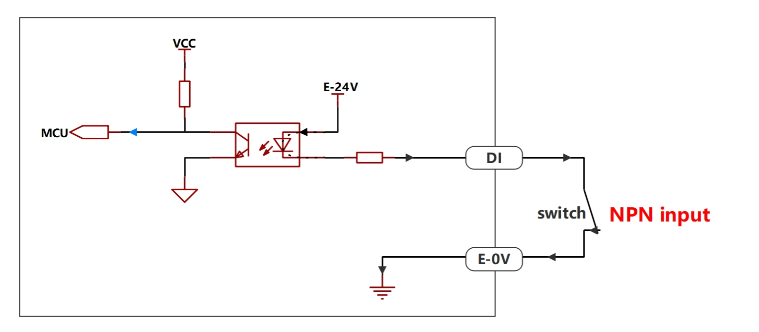
The digital input of DC control box and AC narrow voltage control box only supports NPN type input. The digital input of AC wide voltage control box supports optional NPN and PNP types, with NPN type as the default factory setting.
Control Box Type
Input Type
DC Control Box
NPN Input
AC Narrow Voltage Control Box
NPN Input
AC Wide Voltage Control Box
NPN Input/PNP Input
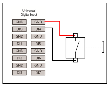
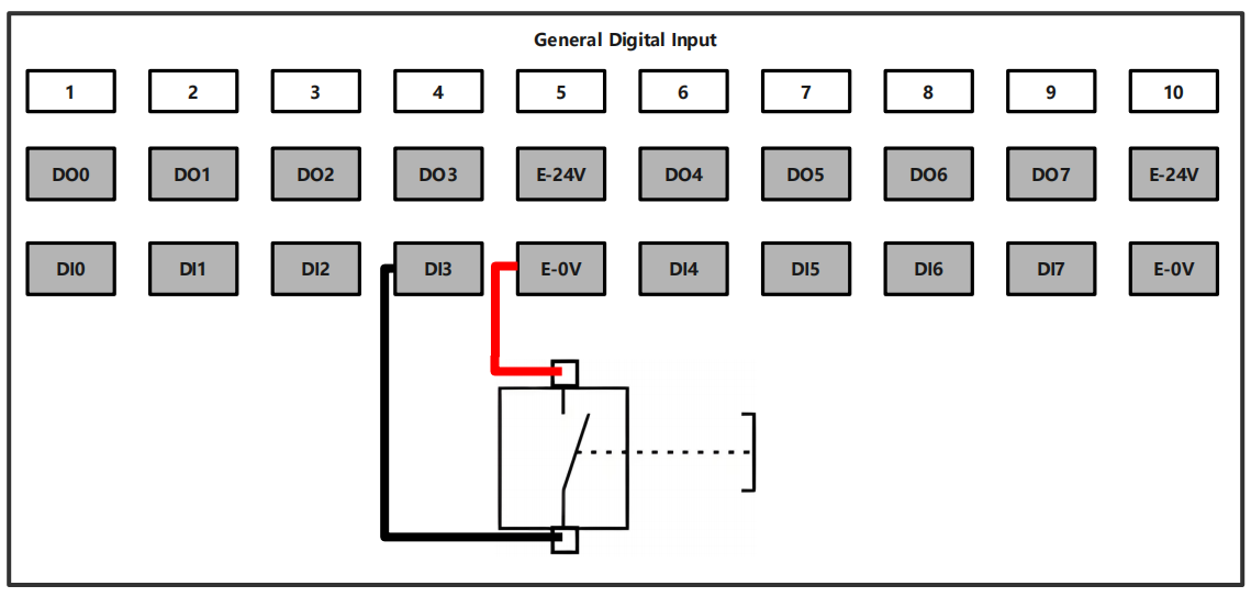
3.3.3.2.3. Wiring Diagram of Digital Input of Control Box
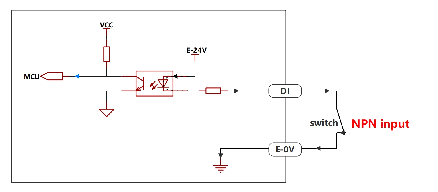
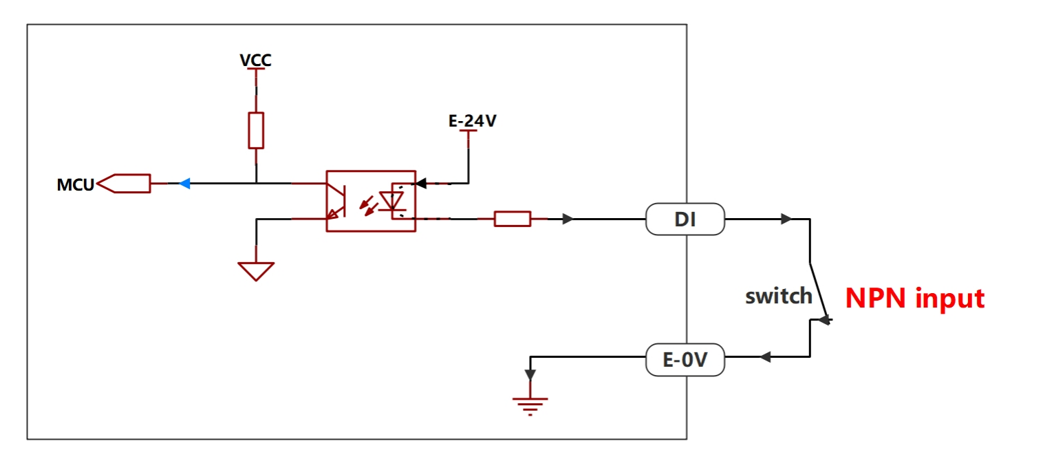
The digital input of DC control box and AC narrow voltage control box only supports NPN type input. The wiring diagram is as follows.
Figure 3.3-2 Wiring Diagram of Digital Input for DC Control Box and AC Narrow Voltage Control Box
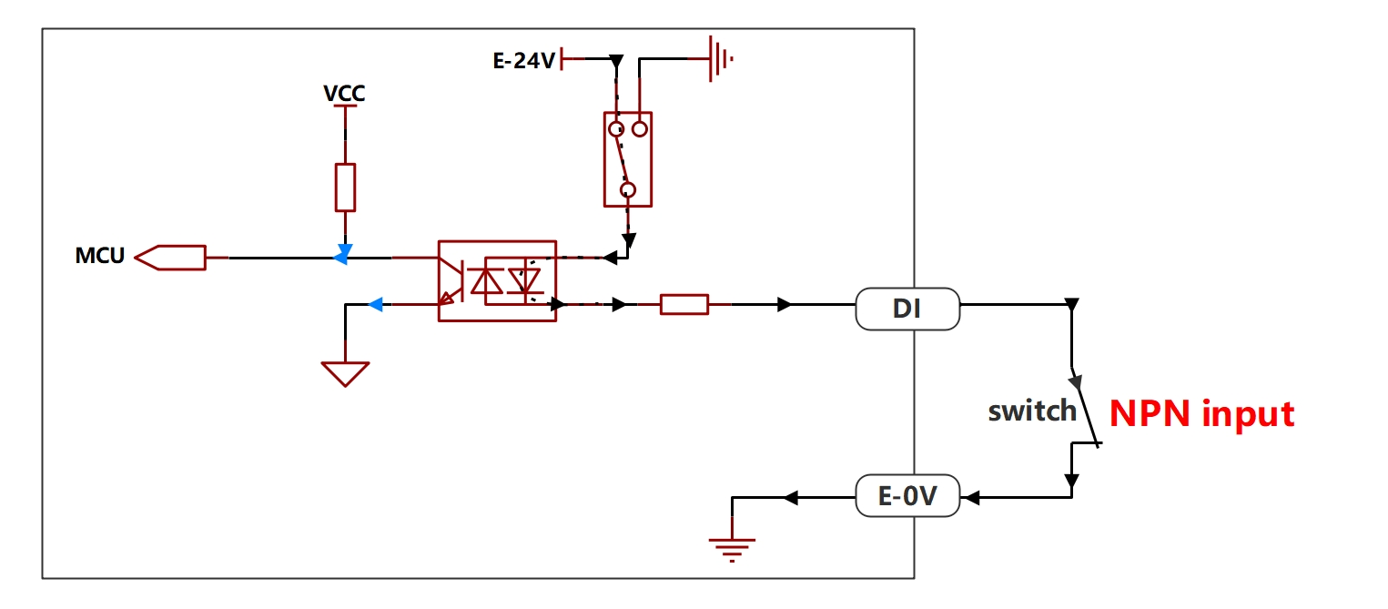
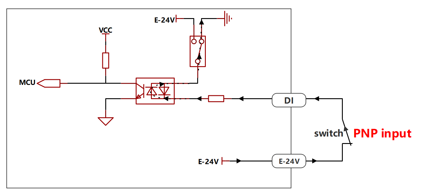
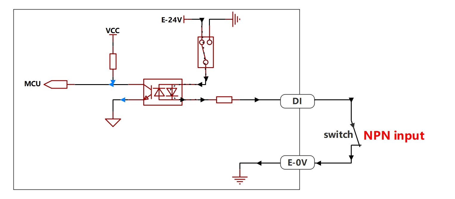
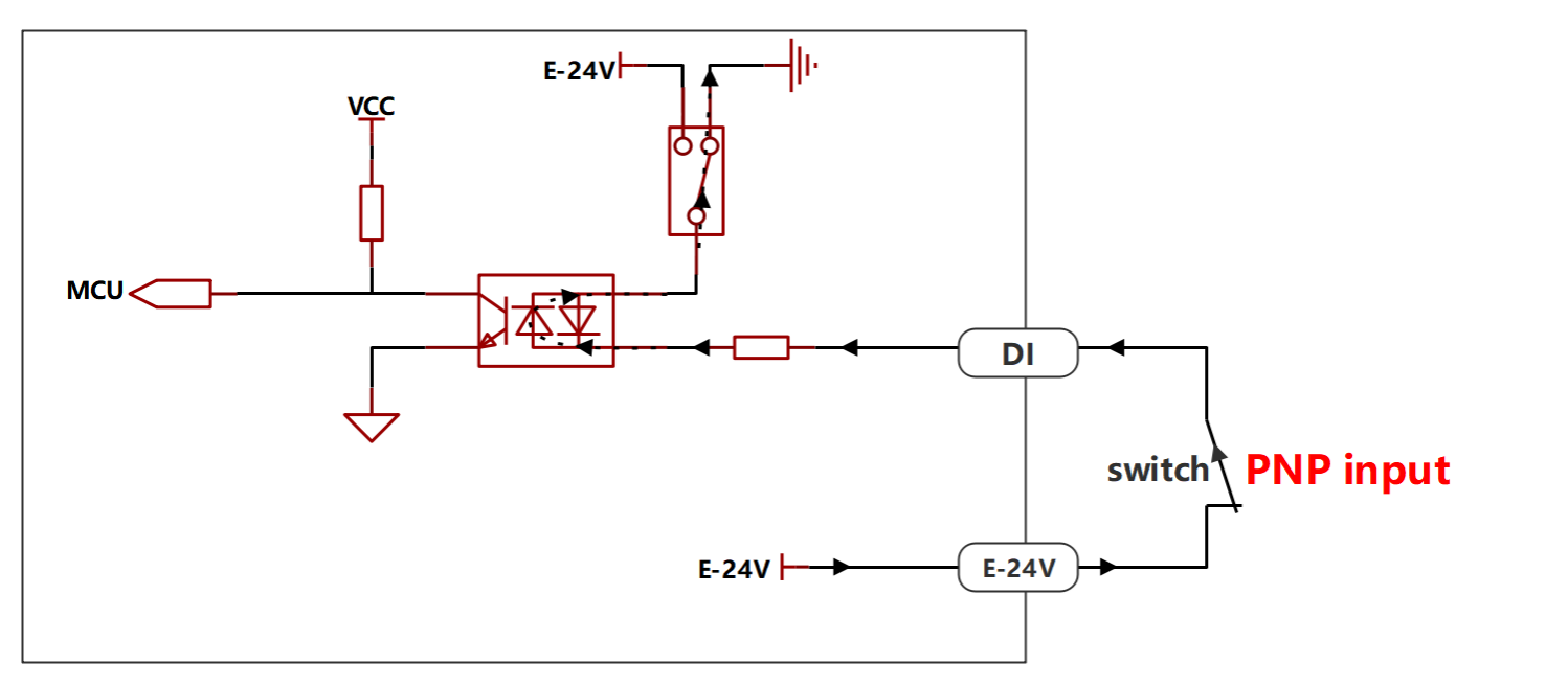
The digital input of AC wide voltage control box supports optional NPN and PNP types, with NPN type as the default factory setting. The wiring diagrams are as follows:
Input Type
Connection Diagram
NPN Input
PNP Input
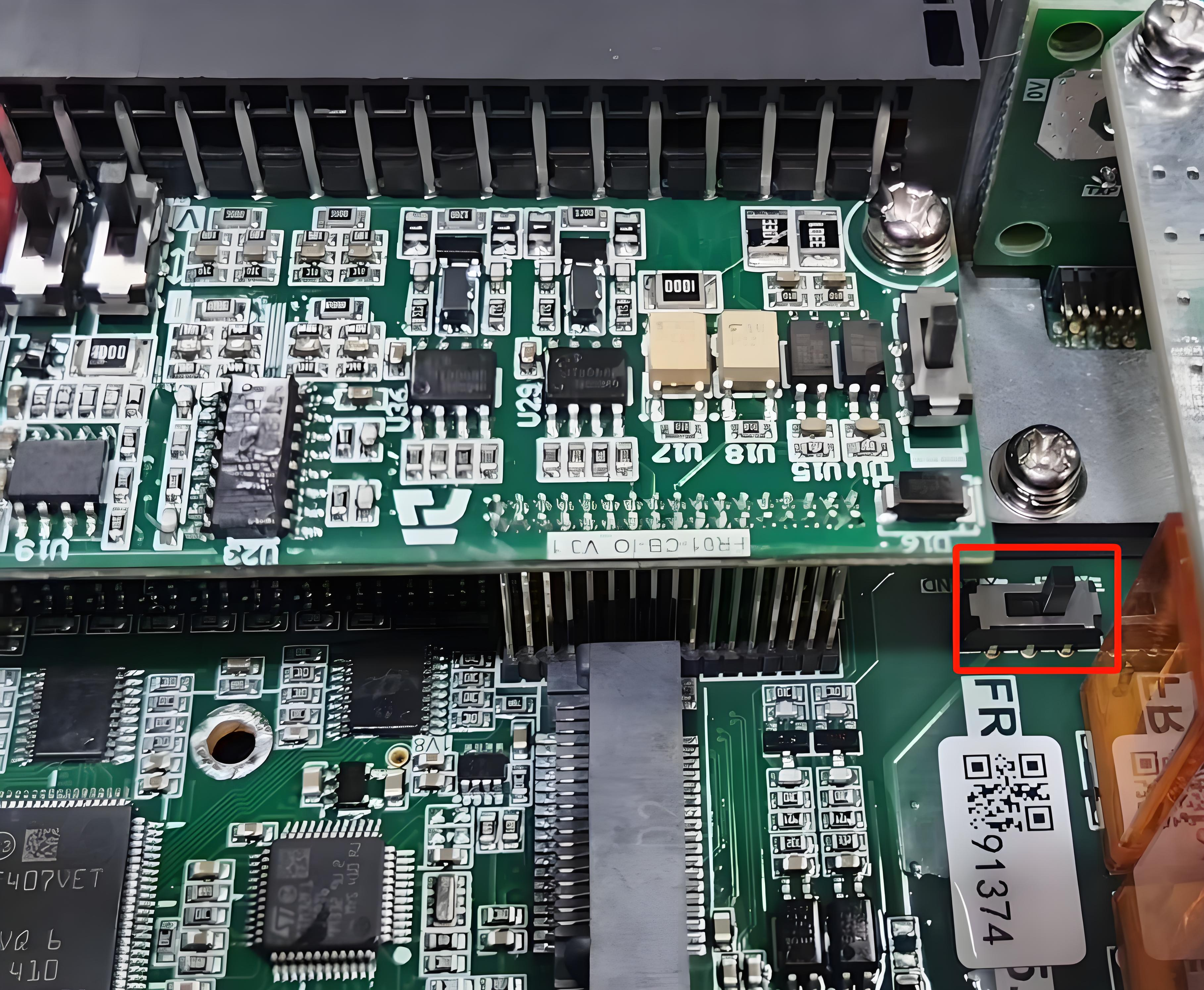
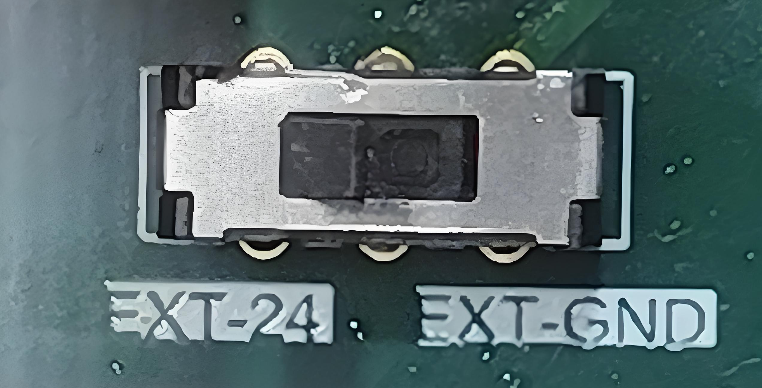
The input type of the wide voltage control box digital input is determined by the DIP switch inside the control box. If the user needs to change the input type, the DIP switch needs to be set to the corresponding position.
DIP Switch Position
DIP Switch Physical Position
NPN Input
EX-24V
PNP Input
EX-0V
3.3.3.2.4. Software Settings Related to Digital Input of Control Box
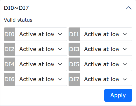
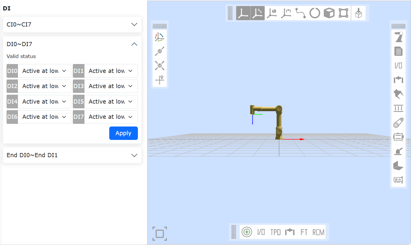
The only software setting item for digital input is “DI0-DI7 General Input Valid Status”, which represents the digital voltage level value corresponding to the detected valid input. This setting allows users to use digital input more flexibly.
Figure 3.3-3 DI0-DI7 General Input Valid Status
The comparison table of valid status detected by the software under different settings of “DI0-DI7 General Input Valid Status” when the external switch of digital input is in different states is as follows:
Table 3.3-2 Valid Status Comparison Table
Control Box Type
Input Type
High Level Valid (Switch Closed)
High Level Valid (Switch Open)
Low Level Valid (Switch Closed)
Low Level Valid (Switch Open)
DC Control Box
NPN Input
Invalid
Valid
Valid
Invalid
AC Narrow Voltage Control Box
NPN Input
Invalid
Valid
Valid
Invalid
AC Wide Voltage Control Box
NPN Input
Invalid
Valid
Valid
Invalid
AC Wide Voltage Control Box
PNP Input
Invalid
Valid
Valid
Invalid
3.3.3.3. Digital Output Description of Control Box
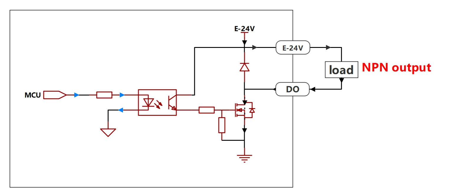
3.3.3.3.1. Summary of Digital Output of Control Box
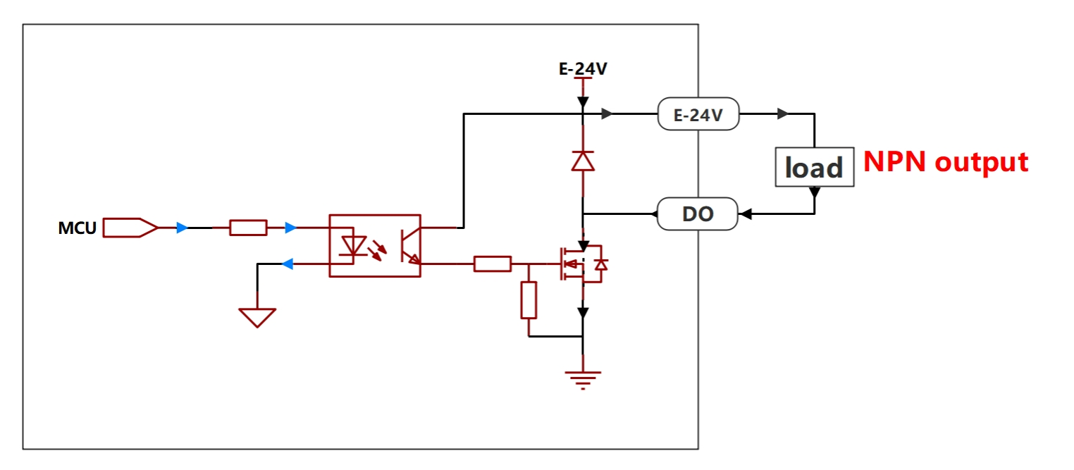
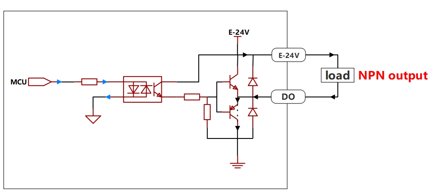
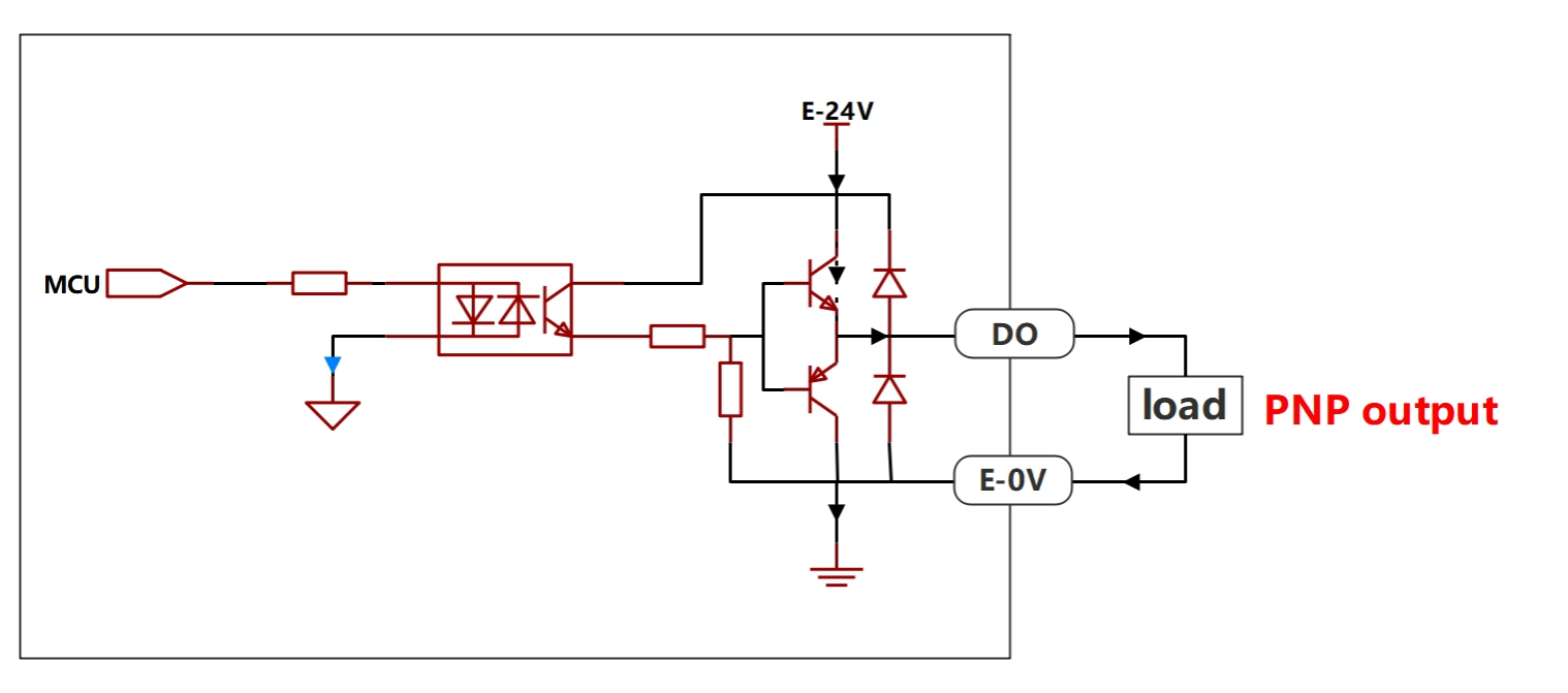
The following lists the output types supported by the digital output of Faro robot integrated mini control box, as well as the corresponding wiring diagrams and configuration comparison tables.
Figure 3.3-4 Control Box DO Output During Power-On
Table 3.3-3 Control Box Digital Output Configuration Comparison Table
Control Box Type
Input Type
Connection Diagram
High Level (Switch Set to ON)
High Level (Switch Set to OFF)
Low Level (Switch Set to ON)
Low Level (Switch Set to OFF)
DC Control Box
NPN Output
Valid
Valid
Invalid
Invalid
AC Narrow Voltage Control Box
NPN Output
Valid
Valid
Invalid
Invalid
AC Wide Voltage Control Box
NPN Output
Valid
Valid
Invalid
Invalid
AC Wide Voltage Control Box
PNP Output
Valid
Valid
Invalid
Invalid
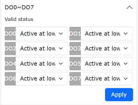
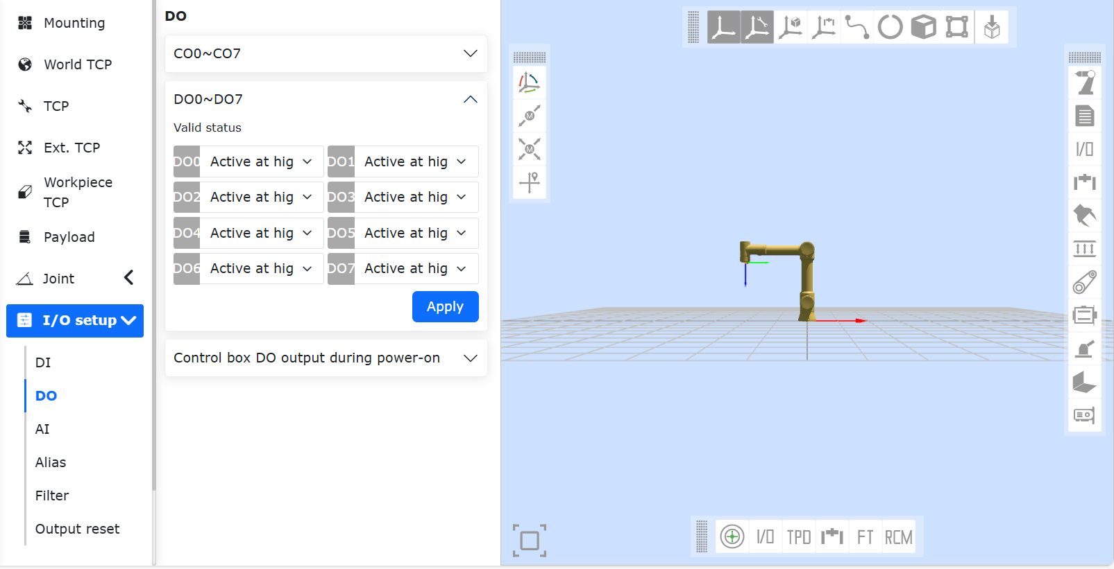
Figure 3.3-5 General Output Valid Status
Table 3.3-4 Control Box Digital Output Configuration Comparison Table
Control Box Type
Input Type
Connection Diagram
High Level Valid (Switch Set to ON)
High Level Valid (Switch Set to OFF)
Low Level Valid (Switch Set to ON)
Low Level Valid (Switch Set to OFF)
DC Control Box
NPN Output
Valid
Invalid
Invalid
Valid
AC Narrow Voltage Control Box
NPN Output
Valid
Invalid
Invalid
Valid
AC Wide Voltage Control Box
NPN Output
Valid
Invalid
Invalid
Valid
AC Wide Voltage Control Box
PNP Output
Valid
Invalid
Invalid
Valid
3.3.3.3.2. Supported Types of Digital Output of Control Box
The digital output of DC control box and AC narrow voltage control box only supports NPN type output. The digital output of AC wide voltage control box supports optional NPN and PNP types, with push-pull structure. It only needs to be wired according to the corresponding wiring diagram without special settings.
Control Box Type
Input Type
DC Control Box
NPN Output
AC Narrow Voltage Control Box
NPN Output
AC Wide Voltage Control Box
NPN Output/PNP Output
3.3.3.3.3. Wiring Diagram of Digital Output of Control Box
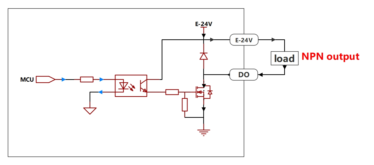
The digital output of DC control box and AC narrow voltage control box only supports NPN type output. The wiring diagram is as follows.
Figure 3.3-6 Wiring Diagram of Digital Output for DC Control Box and AC Narrow Voltage Control Box
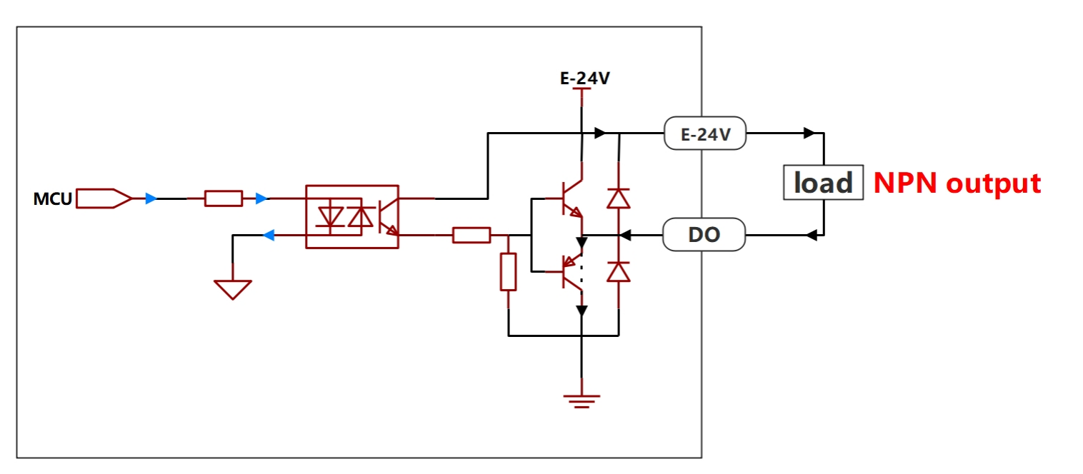
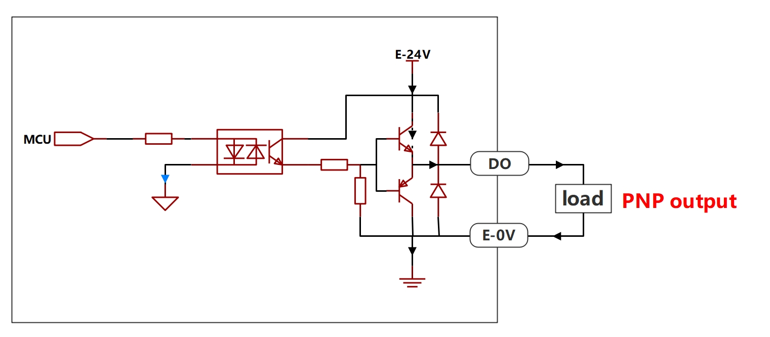
The digital output of AC wide voltage control box supports NPN and PNP types. The wiring diagrams are as follows:
Input Type
Connection Diagram
NPN Input
PNP Input
3.3.3.3.4. Software Settings Related to Digital Output of Control Box
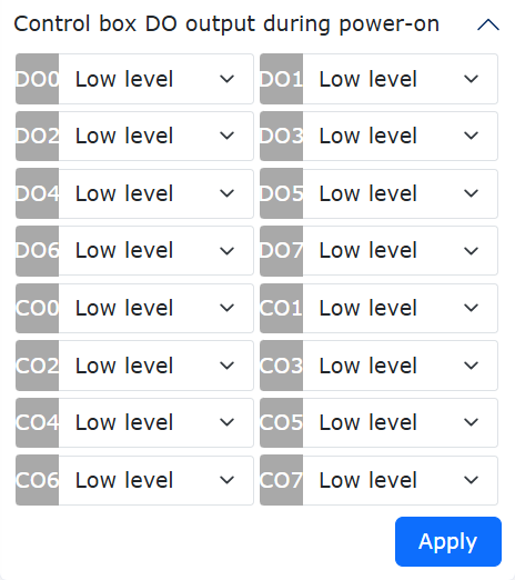
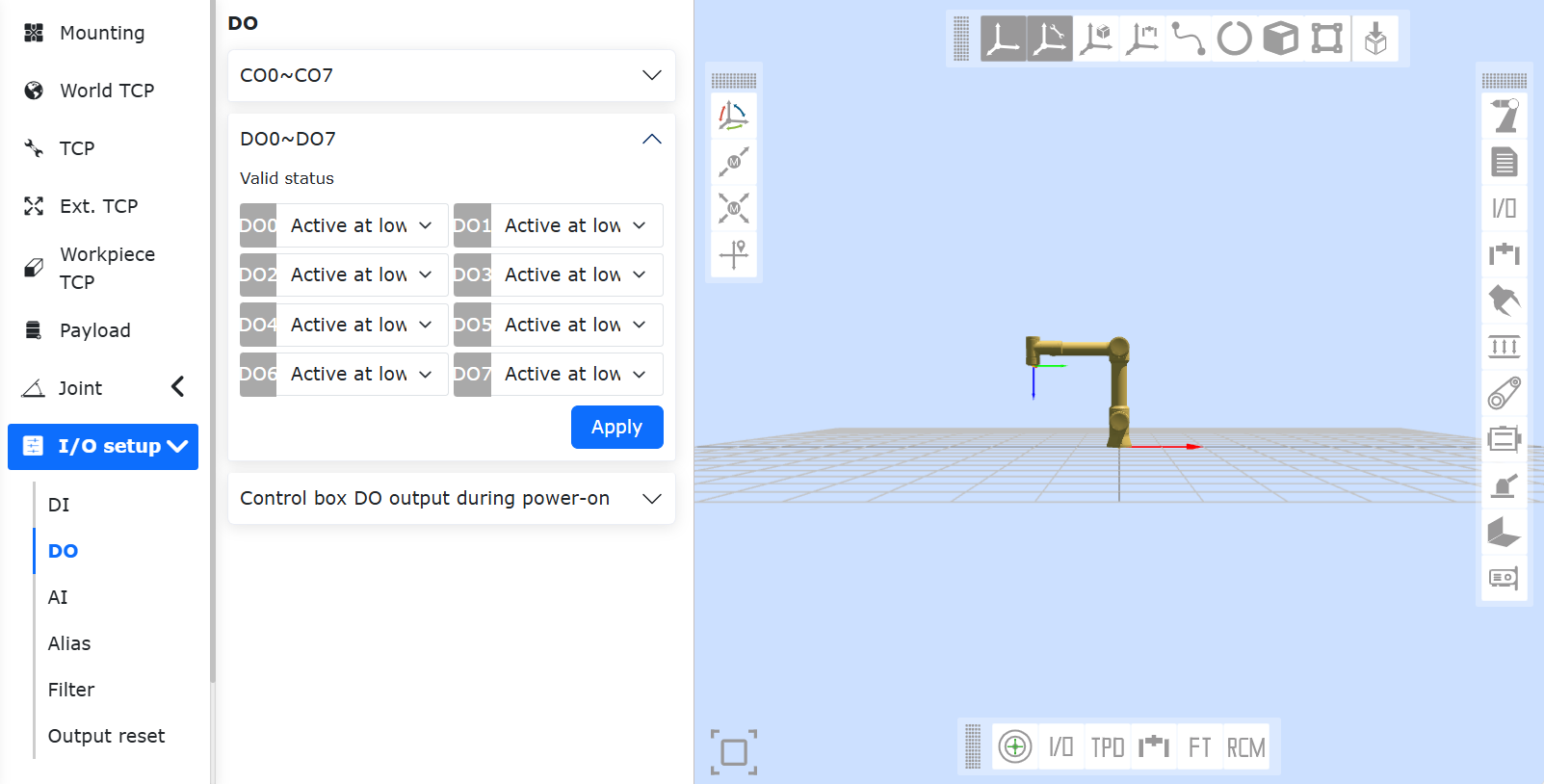
There are two software setting items for digital output: “Control Box DO Output During Power-On” and “DO0-D07 General Output Valid Status”. “Control Box DO Output During Power-On” represents the output level during the power-on period of the control box when the control system has not completed initialization. It can correspond to different output valid states, which can flexibly meet the requirements for output status during power-on. “General Output Valid Status” represents the digital output voltage level value that needs to be controlled when the output is valid. This setting allows users to use digital output more flexibly.
The comparison table of valid status under different settings of “Control Box DO Output During Power-On” is as follows:
Figure 3.3-7 Control Box DO Output During Power-On
Table 3.3-5 Valid Status Comparison Table
Control Box Type
Input Type
High Level Valid (Switch Set to ON)
High Level Valid (Switch Set to OFF)
Low Level Valid (Switch Set to ON)
Low Level Valid (Switch Set to OFF)
DC Control Box
NPN Output
Valid
Valid
Invalid
Invalid
AC Narrow Voltage Control Box
NPN Output
Valid
Valid
Invalid
Invalid
AC Wide Voltage Control Box
NPN Output
Valid
Valid
Invalid
Invalid
AC Wide Voltage Control Box
PNP Output
Valid
Valid
Invalid
Invalid
The comparison table of valid status under different settings of “DO0-D07 General Output Valid Status” is as follows:
Below is a checklist of checklists that FAIRINO Robots recommends performing based on the marked time intervals. If the inspection reveals that the condition of the relevant parts is unqualified, please correct it immediately.
Note
F=Functional check,V=visual inspection,*=Must be checked after severe collision.
Check item
Monthly
Semi-annually
Annually
1
Check joint rear cover *
V
✔
2
Check joint rear cover screws
F
✔
3
Check joint rubber ring
V
✔
4
Check robot cables
V
✔
5
Check robot cable links
V
✔
6
Check robot base mounting bolts *
F
✔
7
Check End Tool Mounting Bolts *
F
✔
Visual inspection
Note
Do not use compressed air to clean robot arms as it may damage components. Do not store the robot for more than 6 months without visual inspection.
If possible, move the robot arm to the zero position.
Turn off and disconnect the power cord of the control box.
Check the cable between the control box and the robot arm for any damage.
Check whether the base mounting bolts are properly tightened.
Check whether the tool flange bolts are properly tightened.
Check whether the flat ring is worn and damaged.
Check all joint backs for any cracks or damage.
Check that the screws for the articulated rear cover are seated and tightened correctly.
Note
If the robot shows any damage during the warranty period, please contact the dealer who purchased the robot.
Function check
The purpose of the functional inspection is to ensure that screws, bolts, tools and robot arms are not loose. The screws/bolts mentioned in the inspection planshall be checked with torque wrenches and the torque shall comply with the standard specifications, which can be found in chapter of the Installation Specifications of the User Manual for the specifications of the mounting bolts of the robot arm.
Cleaning
You can wipe off any dust/dirt/grease observed on the robot arm using a cloth and one of the following cleaners: water, isopropyl alcohol, 10% ethanol or 10% naphtha. If the robot is operating in harsh environments, such as cutting fluids, coolants, etc., it is recommended to clean or replacethe rubber ringregularly.
Do not use bleach. Do not use bleach in any diluted cleaning solution.
In rare cases, a very small amount of grease can be seen from the joint. This does not affect the function, use or longevity of the joint.
3.3.3.4.2. Control box, teaching device, button box
Inspection plan
Below is a checklist of checklists that FAIRINO Robots recommends performing based on the marked time intervals. If the inspection reveals that the condition of the relevant parts is unqualified, please correct it immediately.
Note
F=Functional check,V=Visual inspection.
Check item
Monthly
Semi-annually
Annually
1
Emergency stop button on test button box (teach pendant)
F
✔
2
Safety input and output functions on the test terminal strip
F
✔
3
Detection button box start/stop, mode switching function
F
✔
4
Test button box (teach pendant) cable
V
✔
5
Check and clean the air filter on the control box
V
✔
6
Check whether the terminals of the control box are firm
F
✔
7
Ground resistance of detection control box ≤1Ω
F
✔
8
Check the main power supply of the control box
F
✔
Visual inspection
Unplug the power cord from the control box.
Check that the terminals of the control board are inserted correctly and there are no loose wires.
Check whether there is dirt/dust in the control box. Use an ESD vacuum cleaner for cleaning if necessary.
Note
Do not use compressed air to clean the inside of the control box as this may damage components.
Function check
Note
Robot safety features are important and it is recommended to test once a month to ensure proper functionality.
Emergency stop button onteach pendant/button box:
Press the emergency stop button on the teach pendant/button box.
Observe that the robot stops and turns off the joint power.
Turn on the robot power again.
Other safety inputs and outputs remain operational
Check which safety inputs and outputs are active and whether they can be triggered by PolyScope or external devices.
Date and clock
Check that the date and clock in the Log tab are correct. Incorrect dates and clocks indicate low CMOS battery charge. CMOS batteries have a shelf life of up to5 years.
Check whether the terminal snaps are in place
Cleaning
Teaching device
You may need to clean the teach pendant screen. It is recommended to use a standard mild industrial cleaner that does not contain diluents or any corrosive additives. Do not wipe the screen with abrasive materials. FAIRINO don’t market specific cleaning agents.
The button box
Do not need to be cleaned regularly when it is not normal. If the key identification is blurred and affects the recognition operation, please clean it with detergent at any time.
Control box
The control box contains two filters, one on each side of the control box.
The filter can be observed from the left and right side vents of the control box. Under normal circumstances, you can see the honeycomb structure of the filter.
Remove the filter for cleaning. Clean with low pressure air or change filters as needed. Remember to clean each side. If it is dirty or damaged, replace it (worse, remove the upper cover of the controller and replace the filter from inside the upper cover).
Listen to the sound of the fan when running. If the sound is abnormal, please contact the service provider or replace it.
FR robots need to be disposed of according to the applicable national laws and regulations and national standards. For details, you can contact manufacturers.
The recommended robot installation base meets the following requirements to ensure a secure and stable installation of the robot:
(1)The robot mounting base needs to be strong enough and have sufficient load-bearing capacity, which should be able to bear at least 5 times the weight of the robot and at least 10 times the 1-axis torque.
(2)The surface of the robot mounting base should be flat to ensure close contact with the robot contact surface.
(3)The robot mounting base should have sufficient stiffness, be firmly fixed, and not resonate with the robot.
(4)When the robot and other components are moving simultaneously, the mounting base should be separated from other moving components and not fixed together to avoid vibration interference during the movement process.
(5)If the robot is installed on a mobile platform or external axis, the acceleration of the mobile platform or external axis should be as low as possible.
Warning
The following installation methods should be avoided:
(I)Avoid fixing the robot to other moving devices.
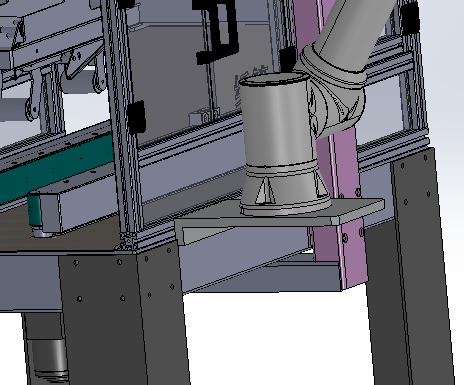
Figure 3.4-1 Avoid installing on other sports equipment
Make sure the robot arm is installed correctly and safely. Unstable installation will cause accidents.
Note
You can purchase accurate bases as attachments. Figure 3.4-2、3.4-5、3.4-8、3.4-11 show the position of the sales hole and the location of the screw.
3.4.1.1. Installation requirements for FR3/FR3-WMS/FR3-WML/FR3-C/FR5-C robot
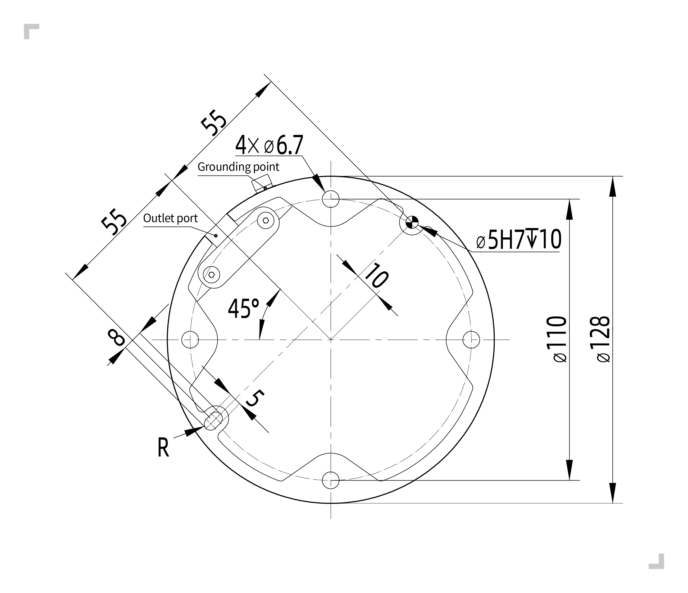
When installing the robot on the mounting base, use four M6 bolts with a strength of not less than 8.8 to fix the robot on the mounting base. The bolts must be tightened with a torque of not less than 10Nm.Suggest using two on the mounting base φ 5mm pin hole matched with pins for robot positioning to improve robot installation accuracy and prevent robot movement due to collisions and other factors.When the robot has high operating accuracy requirements, please be sure to add pins to position the robot.
Figure 3.4-2 FR3/FR3-WMS/FR3-WML/FR3-C/FR5-C model collaborative robot installation size
Important
According to different application scenarios, we recommend several robot installation bases as follows
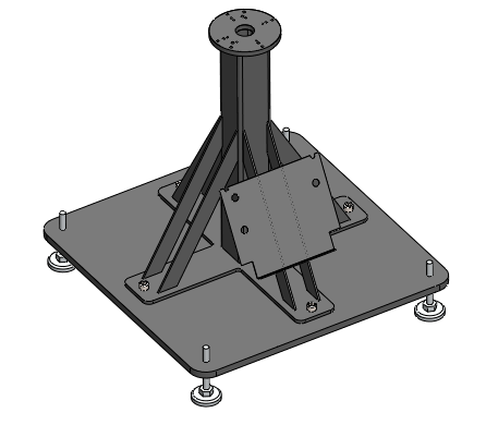
(I)For situations where the motion speed is not too fast, the running speed is not too large, the accuracy requirements are average, and it is not convenient to fix the robot on the ground, the recommended installation base for the robot is as follows.
Figure 3.4-3 FR3/FR3-WMS/FR3-WML/FR3-C/FR5-C model collaborative robot low requirement mounting base
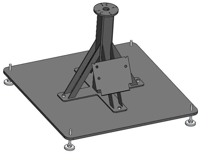
(II)For situations where the motion speed is fast, the running speed is high, and the accuracy requirements are high, it is recommended to install the robot on the following base and fix it on a solid ground.
Figure 3.4-4 FR3/FR3-WMS/FR3-WML/FR3-C/FR5-C Model Collaborative Robot High Demand Mounting Base
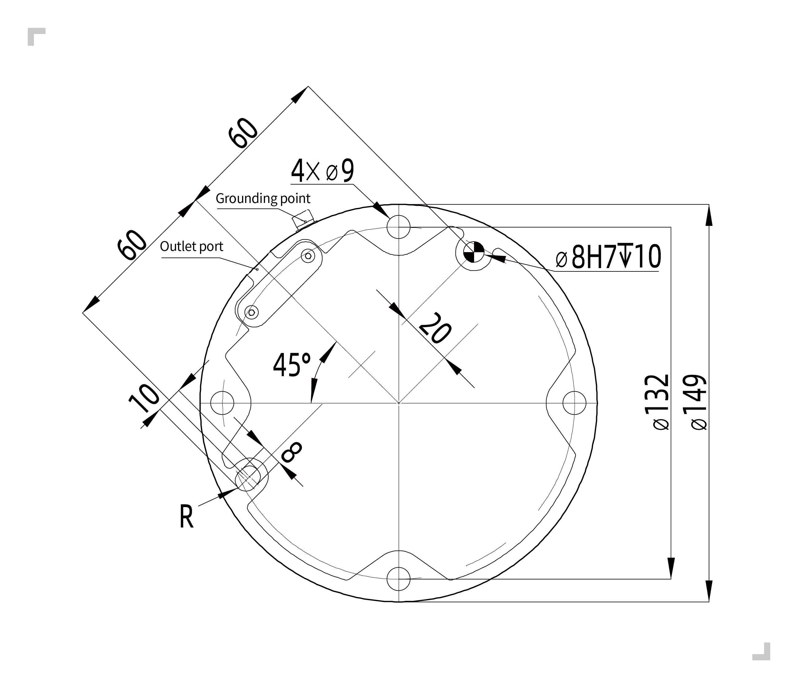
When installing the robot on the mounting base, use four M8 bolts with a strength of not less than 8.8 to fix the robot on the mounting base. The bolts must be tightened with a torque of not less than 20Nm.Suggest using two on the mounting base φ 8mm pin hole matched with pins for robot positioning to improve robot installation accuracy and prevent robot movement due to collisions and other factors.When the robot has high operating accuracy requirements, please be sure to add pins to position the robot.
Figure 3.4-5 FR5 model collaborative robot installation size
Important
According to different application scenarios, we recommend several robot installation bases as follows
(I)For situations where the motion speed is not too fast, the running speed is not too large, the accuracy requirements are average, and it is not convenient to fix the robot on the ground, the recommended installation base for the robot is as follows.
Figure 3.4-6 FR5 Model Collaborative Robot High Demand Mounting Base
(II)For situations where the motion speed is fast, the running speed is high, and the accuracy requirements are high, it is recommended to install the robot on the following base and fix it on a solid ground.
Figure 3.4-7 FR5 model collaborative robot low requirement mounting base
3.4.1.3. Installation requirements for FR10&FR16 robot
When installing the robot on the mounting base, use four M8 bolts with a strength of not less than 8.8 to fix the robot on the mounting base. The bolts must be tightened with a torque of not less than 25Nm.Suggest using two on the mounting base φ 8mm pin hole matched with pins for robot positioning to improve robot installation accuracy and prevent robot movement due to collisions and other factors.When the robot has high operating accuracy requirements, please be sure to add pins to position the robot.
Figure 3.4-8 FR10&FR16 model collaborative robot installation size
Important
According to different application scenarios, we recommend several robot installation bases as follows
(I)For situations where the motion speed is not too fast, the running speed is not too large, the accuracy requirements are average, and it is not convenient to fix the robot on the ground, the recommended installation base for the robot is as follows.
Figure 3.4-9 FR10&FR16 model collaborative robot low requirement mounting base
(II)For situations where the motion speed is fast, the running speed is high, and the accuracy requirements are high, it is recommended to install the robot on the following base and fix it on a solid ground.
Figure 3.4-10 FR10&FR16 Model Collaborative Robot High Demand Mounting Base
3.4.1.4. Installation requirements for FR20&FR30&FR30L robot
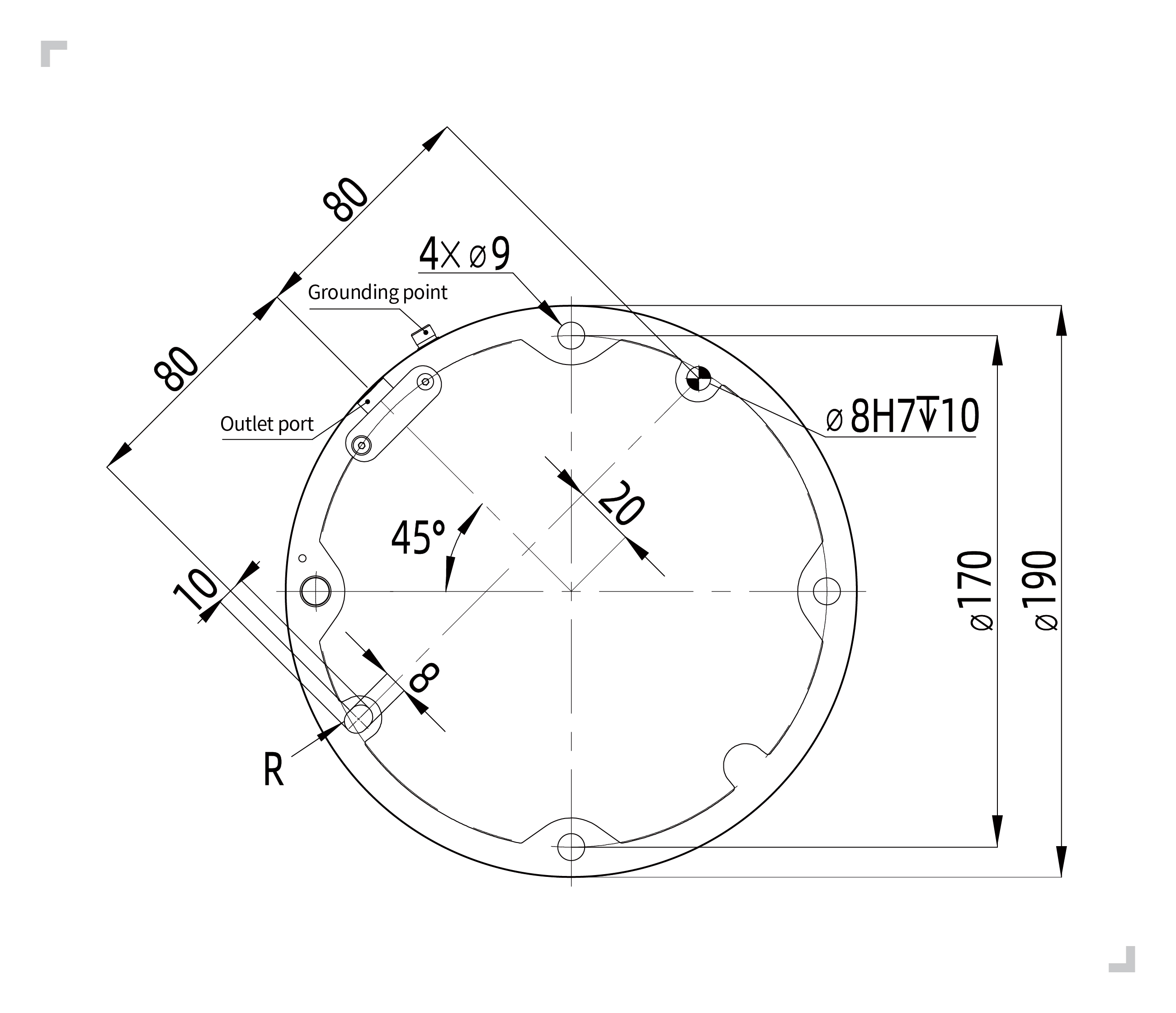
When installing the robot on the mounting base, use six M10 bolts with a strength of not less than 8.8 to fix the robot on the mounting base. The bolts must be tightened with a torque of not less than 45Nm.Suggest using two on the mounting base φ 8mm pin hole matched with pins for robot positioning to improve robot installation accuracy and prevent robot movement due to collisions and other factors.When the robot has high operating accuracy requirements, please be sure to add pins to position the robot.
Figure 3.4-11 FR20&FR30&FR30L model collaborative robot installation size
Important
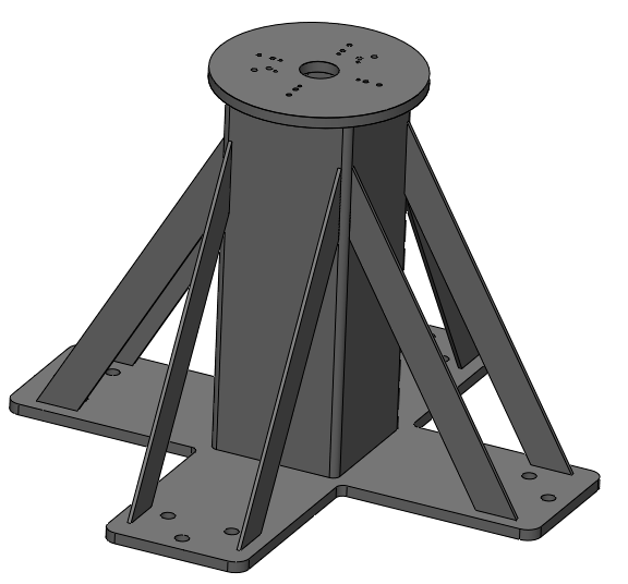
Because the FR20 and FR30 robots have a large weight and running inertia, it is recommended to be directly fixed on the ground. The recommended base is as follows.
Figure 3.4-12 FR20&FR30 model collaborative robot low requirement mounting base
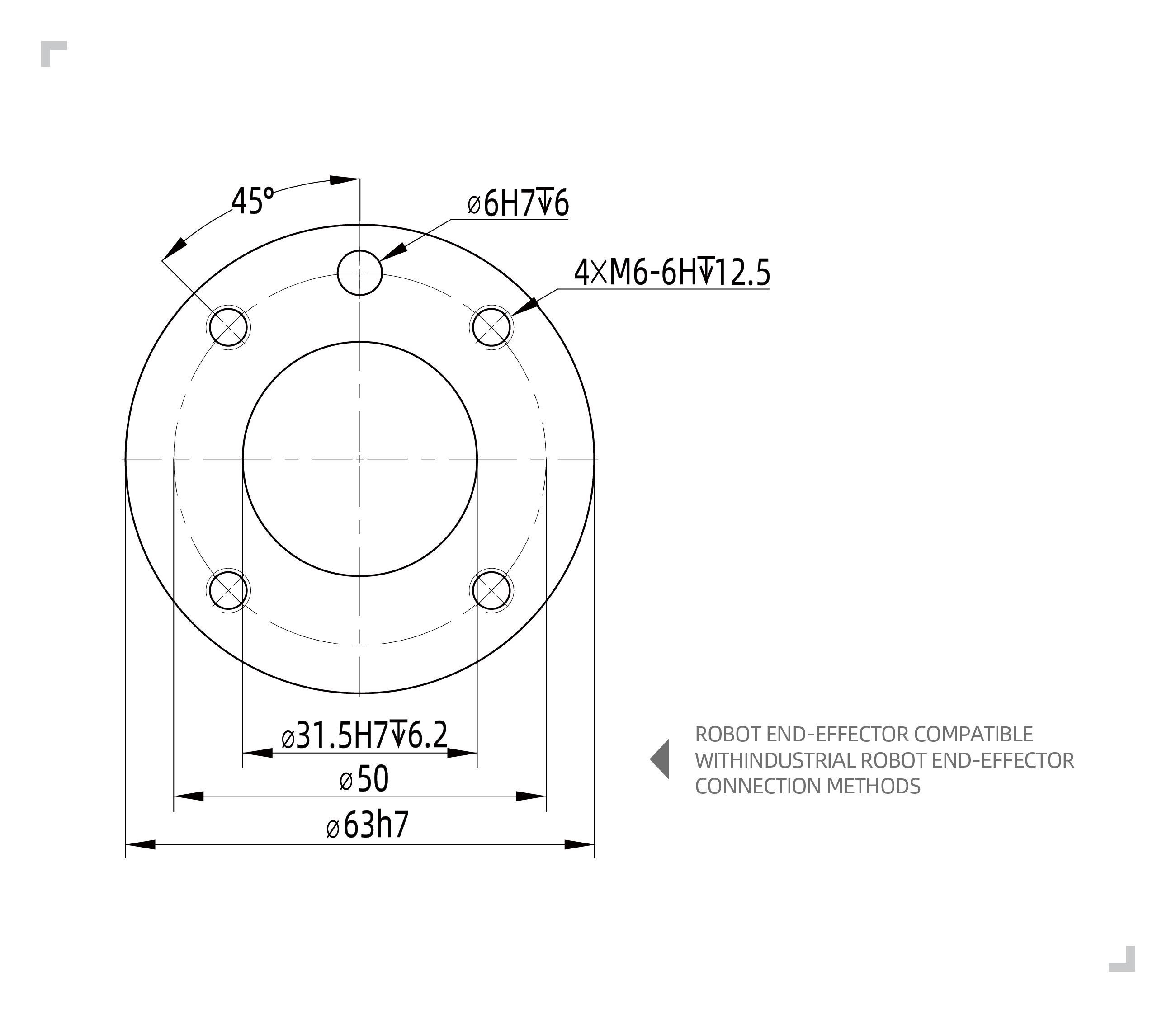
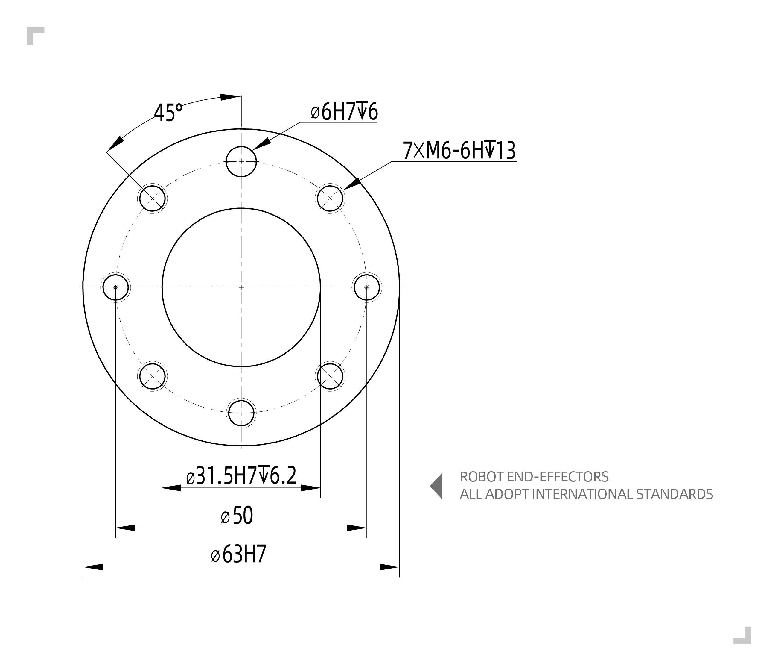
There are four M6 thread holes in the robot tool, which can be used to connect the tool to the robot. The M6 bolt must be tightened with 8nm torque, and its strength level is not less than 8.8. In order to accurately regain the tools, please use the nails in the reserved ø6 sales holes.
Figure 3.4-13 FR3/FR3-WMS/FR3-WML/FR3-C/FR5/FR5-C/FR10/FR16 model robot end flange drawing
Figure 3.4-14 FR20/FR30/FR30L model robot end flange drawing
Important
Make sure the tools are installed correctly and safely.
Ensure the safety architecture of the tools, and no parts of parts fall into danger.
Installing M6 bolts with a length of more than 8mm on the robot flange may destroy tool flanges and cause damage that cannot be repaired, causing a tool to change tools.
When installing and using a collaborative robot, make sure to meet the following requirements:
Environmental temperature 0-45 ℃
Humidity 0% to 90% RH (no condensation)
No mechanical impact and shock
Altitude requires less than 2000M
No corrosive gases, no liquid, no explosive gases, no oil pollution, no salt fog, no dust or metal powder, no radioactive material, no electromagnetic noise, non-flammable items
Avoid the device from working under the unstable conditions of the current
Users need to add an air switch before the robot power supply, and it is recommended to add an EMC filter
Note
If you want to hang or install the collaborative robot, please contact us.
Installing the robot on a strong surface, the surface should be sufficient to withstand the weight of the robotic arm at least 5 times, and the surface cannot be vibrated.
The load curves in this section are based on the tests of each model under specific trajectories. The load curves of each model have two parts: “full performance” and “extended load capacity”, as follows:
The operating environment of “full performance” is: the friction compensation coefficient of each joint is 1; the collision level of each joint is 10; the web interface is set to 100% operating speed and 360deg/s2 acceleration; dynamics 2.0. In this environment, the “full performance” part of the load curve is suitable for most operating trajectories.
If the end load is in the “extended load capacity”, the “time optimal mode” must be turned on and the acceleration limit must be met, or the robot’s working range must be reduced.
The rated payload of the robot depends on the center of gravity offset of the payload, where the center of gravity offset is defined as the distance between the center of the end flange and the center of gravity of the attached payload.
3.4.5.2.1. FR3 Model Collaborative Robot Load Curve
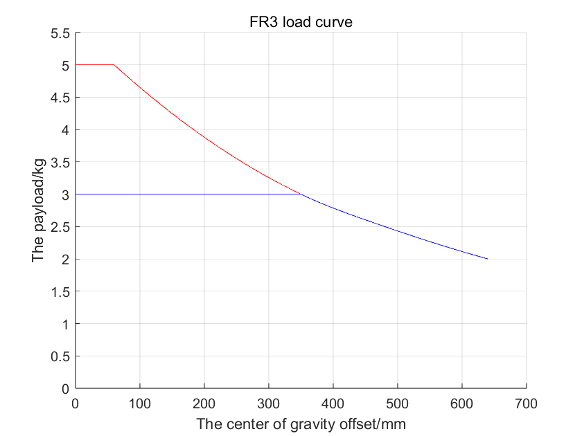
The maximum load that the FR3 collaborative robot can carry is 5kg, and the rated load is 3kg. The load curve is shown in Figure 1. The specific interpretation of the load curve is as follows:
FR3 can carry a load of 3kg or less at full performance, see the “blue envelope”;
When the load is 3kg to 5kg, it is the extended load capacity, see the “red envelope”, at this time the robot can operate in the following states:
① Turn on the “time optimal mode”, it is recommended to set the acceleration to less than 360deg/s2;
② Reduce the robot’s working range or reduce the operating speed.
Figure 3.4-15 FR3 Model Collaborative Robot Load Curve
3.4.5.2.2. FR3-WMS Model Collaborative Robot Load Curve
The maximum load that the FR3-WMS collaborative robot can carry is 5kg, and the rated load is 3kg. The load curve is shown in Figure 1. The specific interpretation of the load curve is as follows:
FR3-WMS can carry a load of 3kg or less at full performance, see the “blue envelope”;
When the load is 3kg to 5kg, it is the extended load capacity, see the “red envelope”, at this time the robot can operate in the following states:
① Turn on the “time optimal mode”, it is recommended to set the acceleration to less than 360deg/s2;
② Reduce the robot’s working range or reduce the operating speed.
Figure 3.4-16 FR3-WMS Model Collaborative Robot Load Curve
3.4.5.2.3. FR3-WML Model Collaborative Robot Load Curve
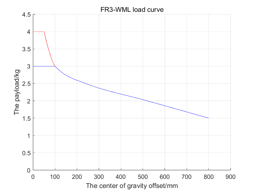
The maximum load that the FR3-WML collaborative robot can carry is 4kg, and the rated load is 3kg. The load curve is shown in Figure 1. The specific interpretation of the load curve is as follows:
FR3-WML can carry a load of 3kg or less at full performance, see the “blue envelope”;
When the load is 3kg to 4kg, it is the extended load capacity, see the “red envelope”, at this time the robot can operate in the following states:
① Turn on the “time optimal mode”, it is recommended to set the acceleration to less than 360deg/s2;
② Reduce the robot’s working range or reduce the operating speed.
Figure 3.4-17 FR3-WML Model Collaborative Robot Load Curve
3.4.5.2.4. FR3-C Model Collaborative Robot Load Curve
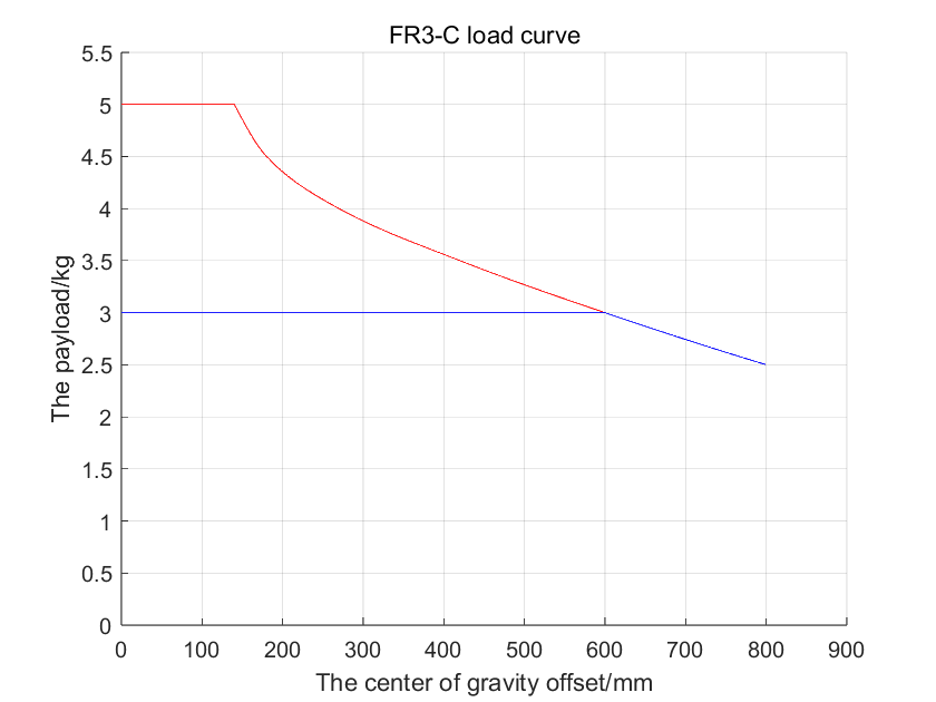
The maximum load that the FR3-C collaborative robot can carry is 5kg, and the rated load is 3kg. The load curve is shown in Figure 1. The specific interpretation of the load curve is as follows:
FR3-C can carry a load of 3kg or less at full performance, see the “blue envelope”;
When the load is 3kg to 5kg, it is the extended load capacity, see the “red envelope”, at this time the robot can operate in the following states:
① Turn on the “time optimal mode”, it is recommended to set the acceleration to less than 360deg/s2;
② Reduce the robot’s working range or reduce the operating speed.
Figure 3.4-18 FR3-C Model Collaborative Robot Load Curve
3.4.5.2.5. FR5 Model Collaborative Robot Load Curve
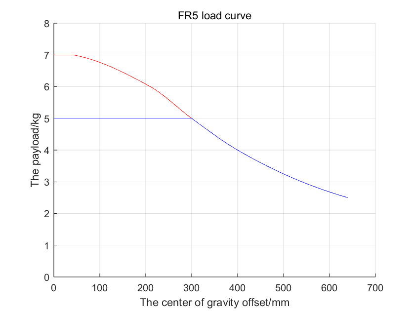
The maximum load that the FR5 collaborative robot can carry is 7kg, and the rated load is 5kg. The load curve is shown in the figure. The specific interpretation of the load curve is as follows:
FR5 can carry a load of 5kg or less at full performance, see the “blue envelope”;
When the load is 5kg to 7kg, it is the extended load capacity, see the “red envelope”, at this time the robot can operate in the following states:
① Turn on the “time optimal mode”, it is recommended to set the acceleration to less than 360deg/s2;
② Reduce the robot’s working range or reduce the running speed.
Figure 3.4-19 FR5 Model Collaborative Robot Load Curve
3.4.5.2.6. FR5-WML Model Collaborative Robot Payload Curve
The FR5-WML model collaborative robot has a maximum payload capacity of 7kg and a rated payload of 5kg. The payload curve is shown in the figure. The specific interpretation of the payload curve is as follows:
Within the “blue envelope”: Full performance - can run most trajectories with friction compensation coefficients all at 1, dynamics 2.0, 100% speed, 360 deg/s² acceleration (maintenance mode).
Within the “red envelope”: Extended payload capacity - can operate under the following conditions:
① Enable “Time-optimal Mode”;
② Reduce robot working range or lower operating speed.
Figure 3.4-20 FR5-WML Model Collaborative Robot Payload Curve
3.4.5.2.7. FR5-C Model Collaborative Robot Load Curve
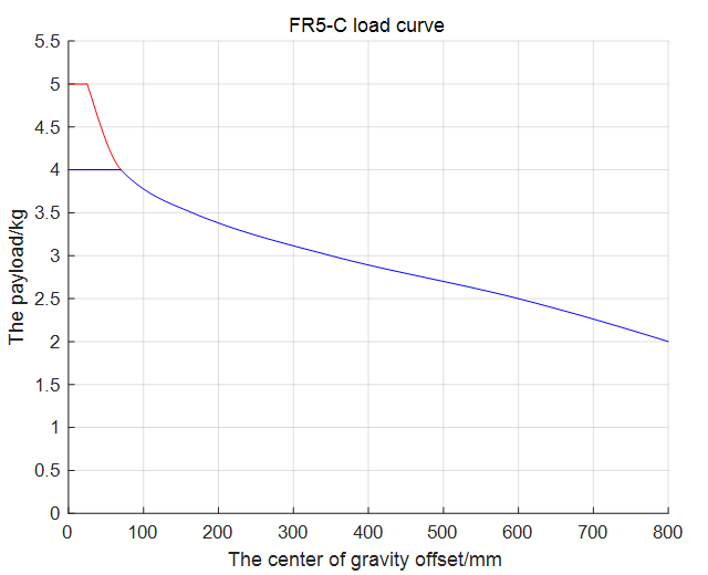
The FR5-C model collaborative robot has a maximum payload of 5kg and a rated payload of 4kg. The load curve is shown in the figure as “Full Performance”.
Figure 3.4-21 FR5-C Model Collaborative Robot Load Curve
3.4.5.2.8. FR10 Model Collaborative Robot Load Curve
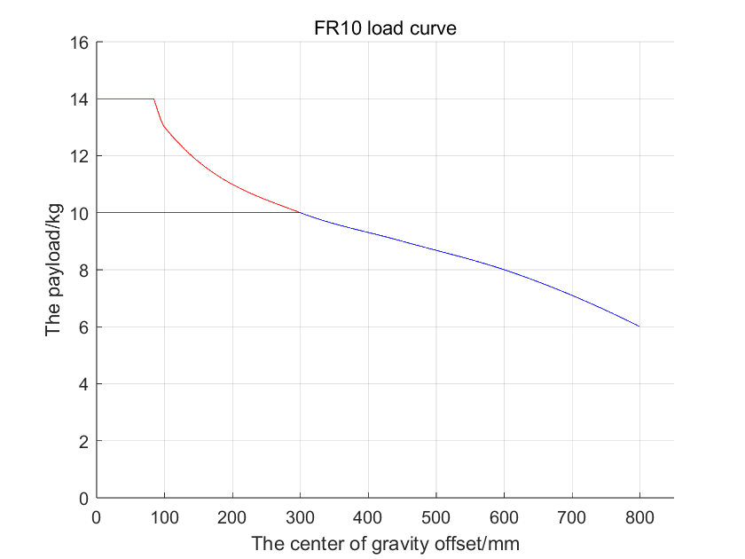
The maximum load that the FR10 collaborative robot can carry is 14kg, and the rated load is 10kg. The load curve is shown in Figure 3. The specific interpretation of the load curve is as follows:
FR10 can carry a load of 10kg or less at full performance, see the “blue envelope”;
When the load is 10kg to 14kg, it is the extended load capacity, see the “red envelope”, at this time the robot can operate in the following states:
① Turn on the “time optimal mode”, it is recommended to set the acceleration to less than 180deg/s2;
② Reduce the robot’s working range or reduce the operating speed.
Figure 3.4-22 FR10 Model Collaborative Robot Load Curve
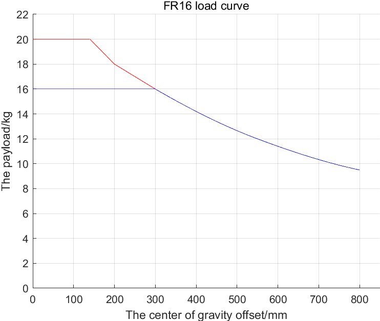
3.4.5.2.9. FR16 Model Collaborative Robot Load Curve
The maximum load that the FR16 collaborative robot can carry is 20kg, and the rated load is 16kg. The load curve is shown in the figure. The specific interpretation of the load curve is as follows:
FR16 can carry a load of 16kg or less at full performance, see the “blue envelope”;
When the load is 16kg to 20kg, it is the extended load capacity, see the “red envelope”, and the robot can operate in the following states:
① Turn on the “time optimal mode”, and it is recommended to set the acceleration to less than 180deg/s2;
② Reduce the robot’s working range or reduce the operating speed.
Figure 3.4-23 FR16 Model Collaborative Robot Load Curve
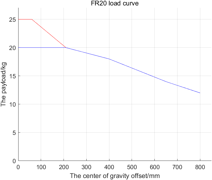
3.4.5.2.10. FR20 Model Collaborative Robot Load Curve
The maximum load that the FR20 collaborative robot can carry is 25kg, and the rated load is 20kg. The load curve is shown in the figure. The specific interpretation of the load curve is as follows:
FR20 can carry a load of 20kg or less at full performance, see the “blue envelope”;
When the load is 20kg to 25kg, it is the extended load capacity, see the “red envelope”, at this time the robot can operate in the following states:
① Turn on the “time optimal mode”, it is recommended to set the acceleration to less than 150deg/s2;
② Reduce the robot’s working range or reduce the operating speed.
Figure 3.4-24 FR20 Model Collaborative Robot Load Curve
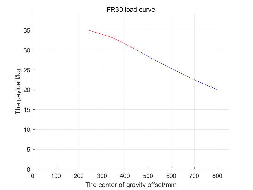
3.4.5.2.11. FR30 Model Collaborative Robot Load Curve
The maximum load that the FR30 collaborative robot can carry is 35kg, and the rated load is 30kg. The load curve is shown in the figure.
FR30 can carry a load of 30kg or less at full performance, see the “blue envelope”;
When the load is 30kg to 35kg, it is the extended load capacity, see the “red envelope”, at this time the robot can operate in the following states:
① Turn on the “time optimal mode”, it is recommended to set the acceleration to less than 150deg/s2;
② Reduce the robot’s working range or reduce the operating speed.
Figure 3.4-25 FR30 Model Collaborative Robot Load Curve
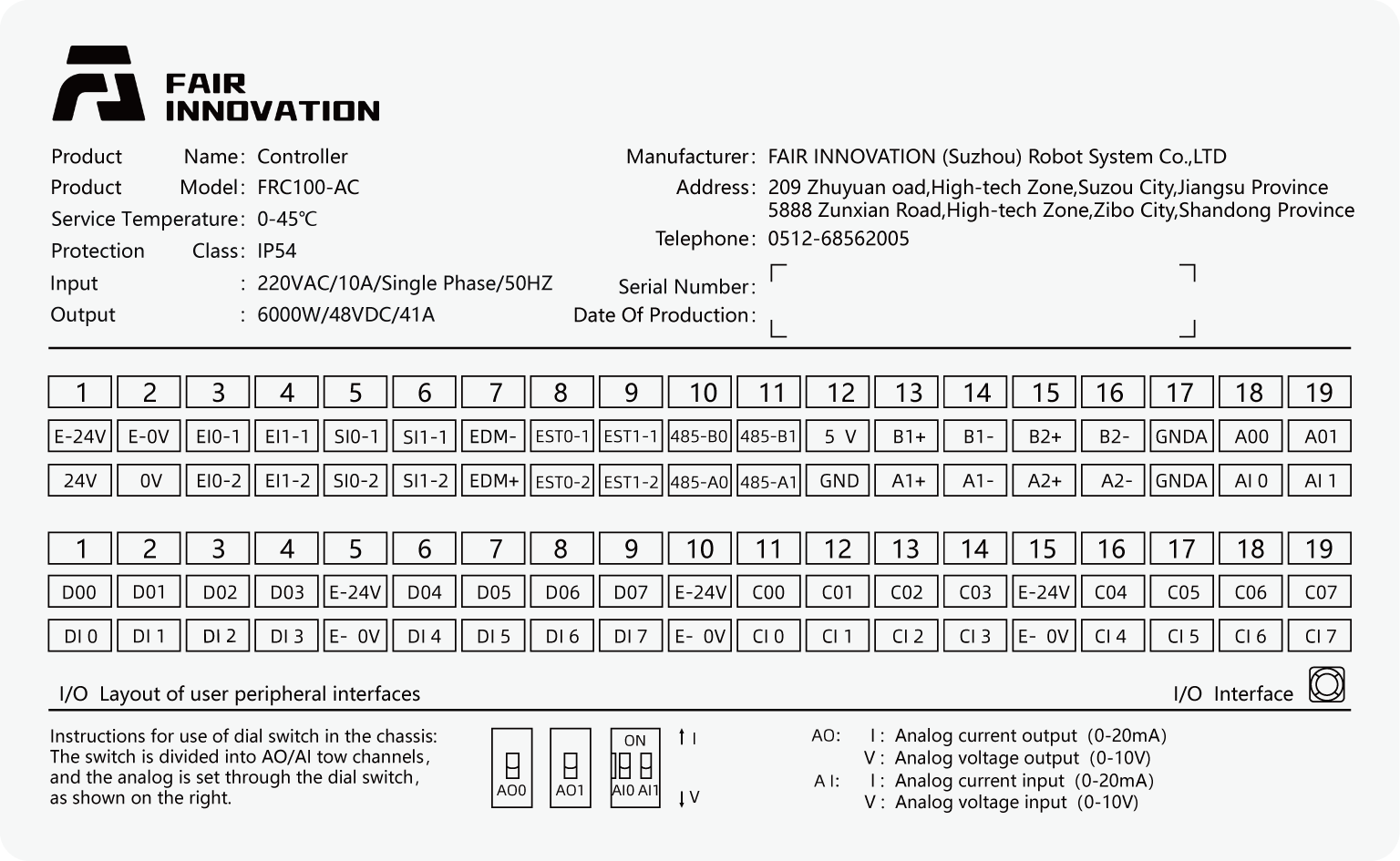
This series of robots can be equipped with three control boxes with different power inputs. For details on the control box power input, refer to the control box nameplate information. The robot needs to be electrically grounded.
Maximum Input (for customers to configure the front-stage power supply)
Maximum output Output (maximum output peak)
DC 2kW
30-60VDC/30A
2000W/48VDC/41A
DC 5kW
30-60VDC/40A
5000W/48VDC/104A
AC narrow voltage 2kW
176-264VDC/10A/Single Machine/50Hz
2000W/48VDC/41A
AC wide voltage 2kW
100-240VDC/10A/Single Machine/50-60Hz
2000W/48VDC/41A
AC wide voltage 5kW
100-240VDC/16A/Single Machine/50-60Hz
5000W/48VDC/104A
Warning
Before wiring, please ensure that the power supply is turned off and hang a safety warning sign next to it.
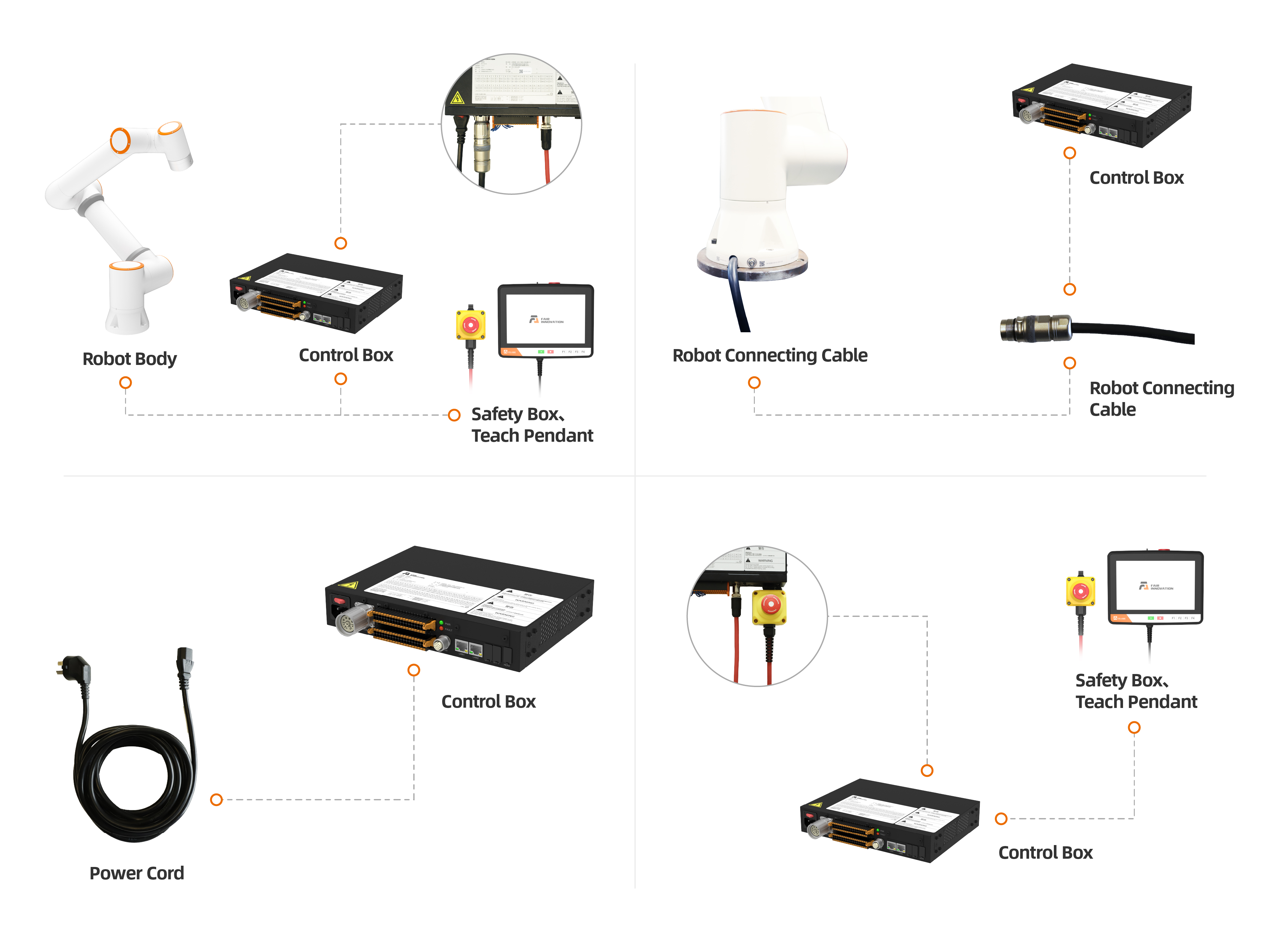
The external wiring of this series of robotic arm control systems is connected using pluggable and quickly installable plugs. The wiring panel of the collaborative robot is shown in Figure 3.5-1.
Make sure the power button on the control box is off (the button is turned to 0) and connect the power cord to the power socket.
Connect the robot body overload cable to the control box overload interface.
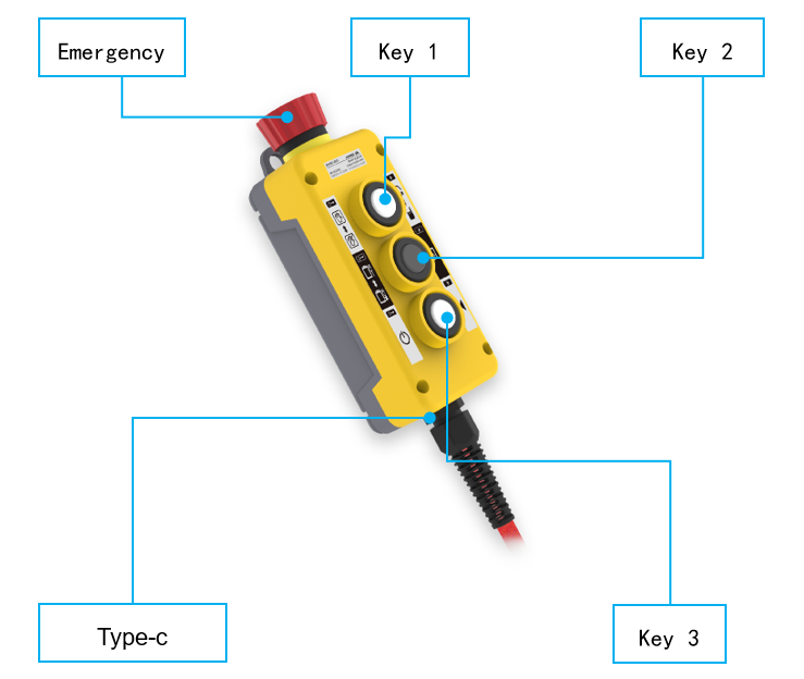
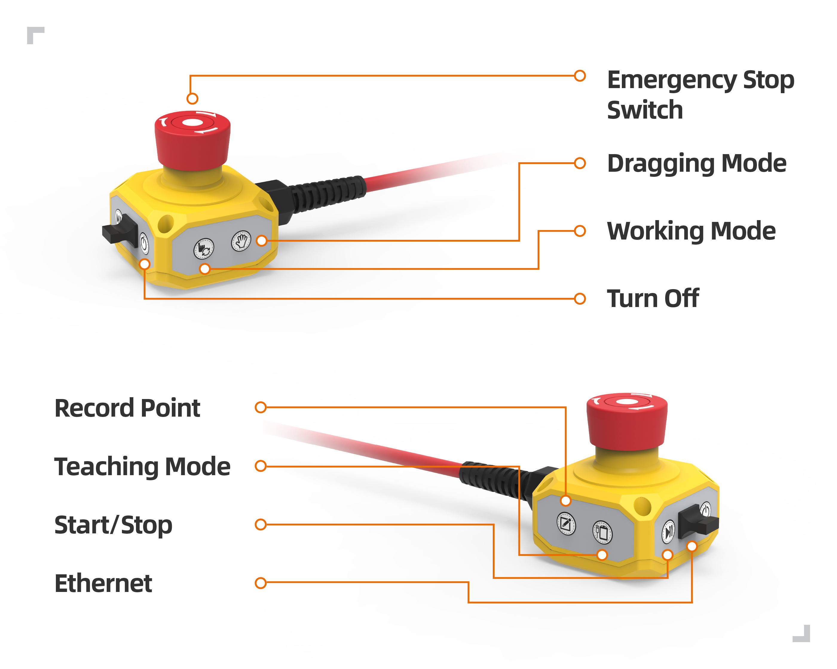
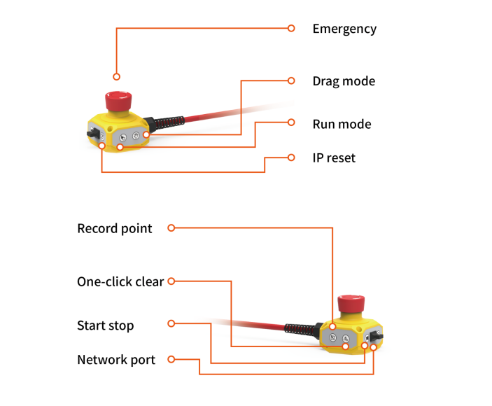
Insert the button box aviation plug into the control box teaching device interface.
The heat dissipation ports on both sides of the control box should be spaced at least 15CM apart.
At the front of the control box (user Table metal, switch power button, heavy load and teaching pendant wiring harness), the spacing distance should not be less than 25CM.
The control box is 0.6-1.5m above the ground.
Do not allow users to replace power cables on their own.
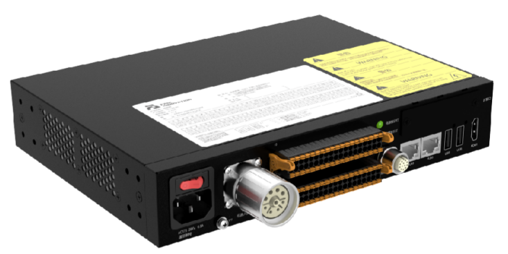
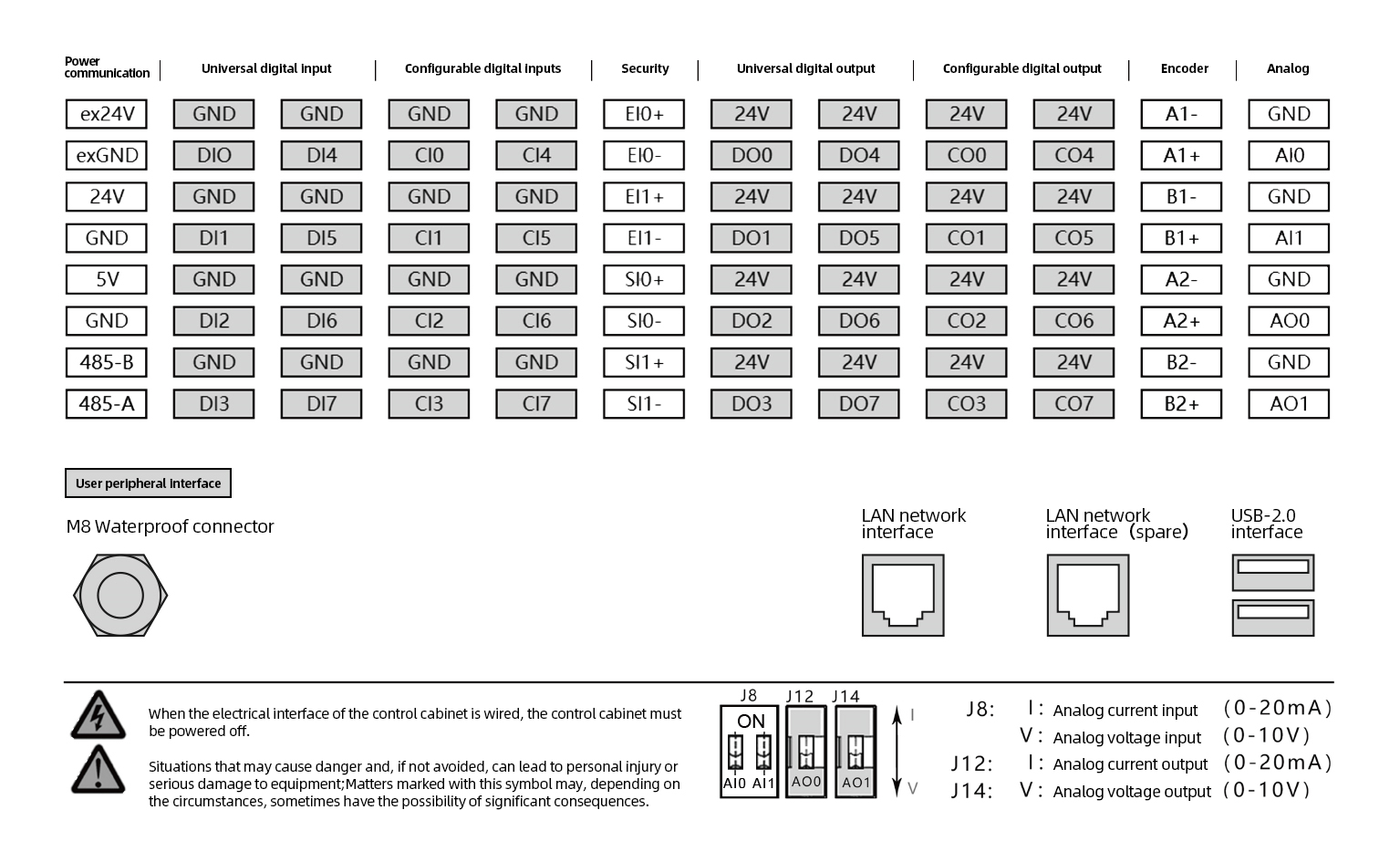
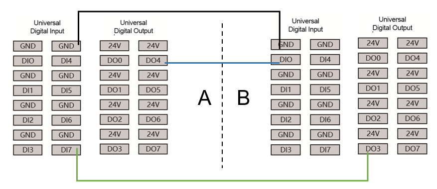
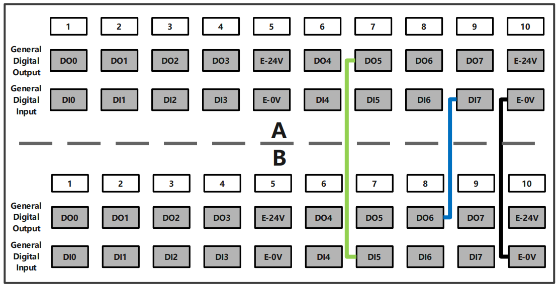
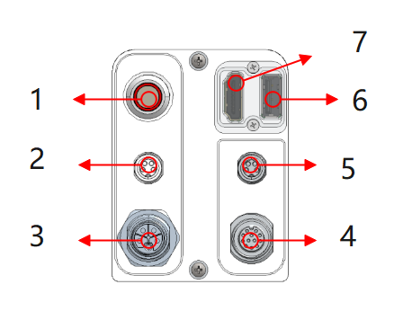
You can use the I/O inside the control box to control various devices, including pneumatic relays, PLCs, and limit switches and stop buttons. Figure 3.5-2 shows the electrical interface group of the control box, and Figure 3.5-3 shows the electrical interface group of the integrated mini control box (mini BOX).
Figure 3.5-2 Schematic Diagram of Control Box Electrical Interface
Figure 3.5-3 Schematic Diagram of Integrated Mini Control Box (mini BOX) Electrical Interface
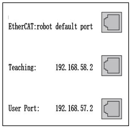
The network interface group address in the control box is shown in figure below. Note that the graph corresponds to the sequence of the address order of the internal network port of the control box, and the default port of the robot is prohibited from insertion. The user’s network port can be used to communicate with the camera and other devices. The IP address is 192.168.57.2. The button box interface is default to the faculty control port, and the IP address is 192.168.58.2. Use the network cable connection button box interface and computer. The computer IP address is set to 192.168.58.10 or the same network segment as it. You can access the teaching pendant page. Easy to manufacture control boxes to access the pages of the oscillator through the network port of the connection button box.
Figure 3.5-4 Significant diagram of network interface group
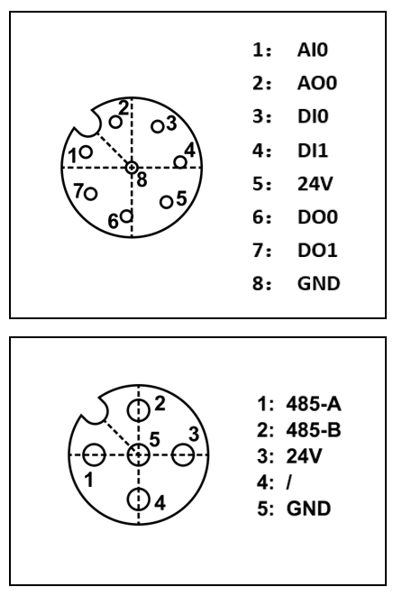
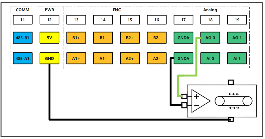
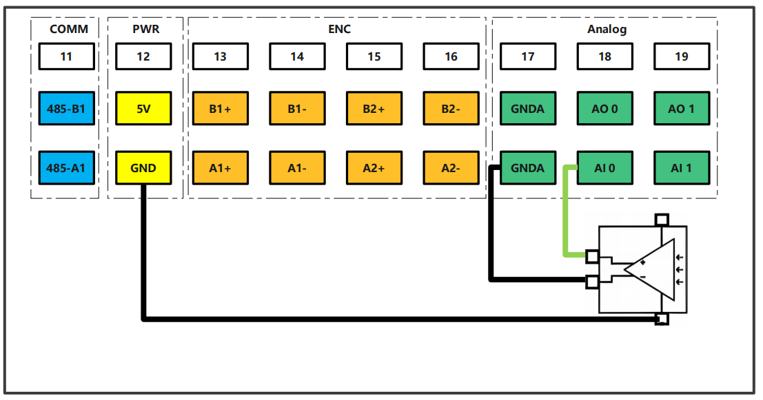
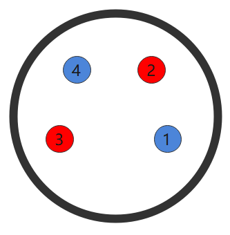
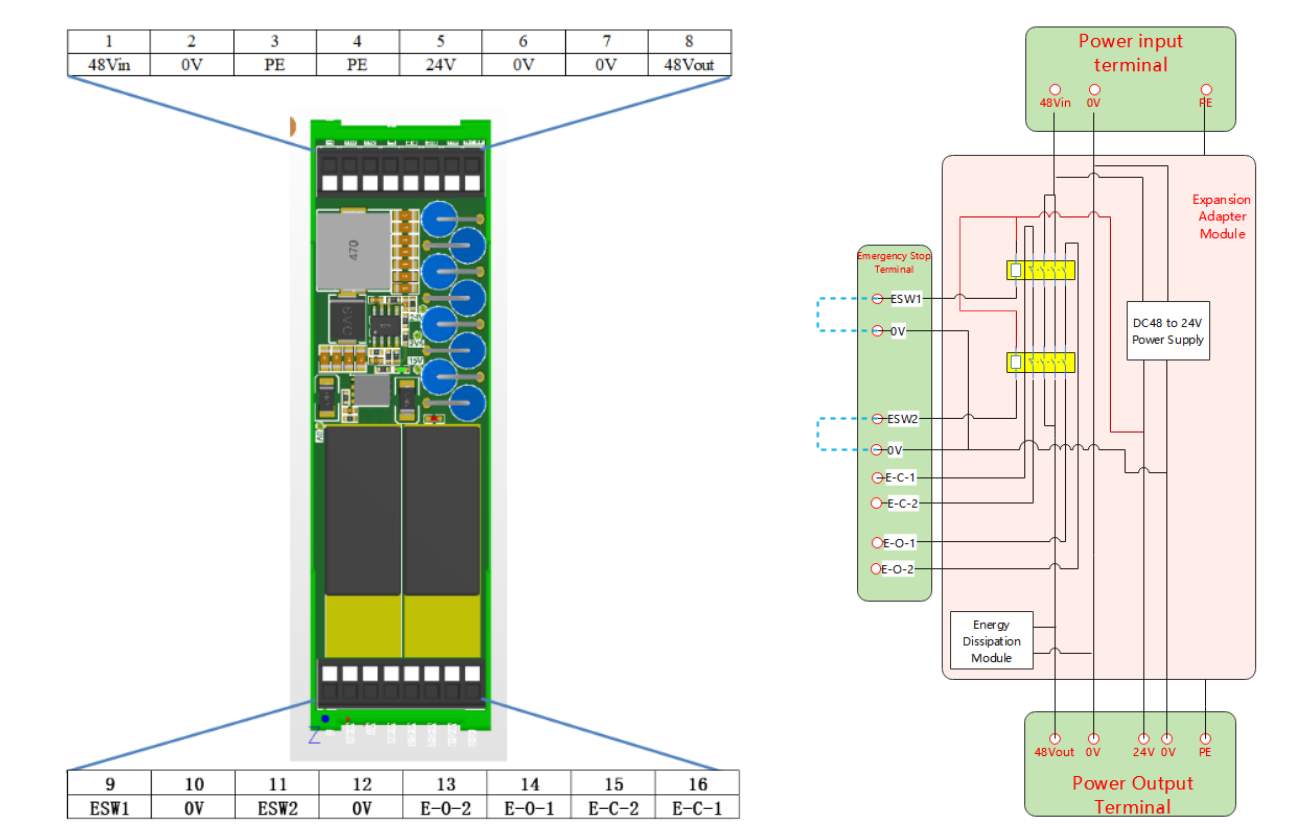
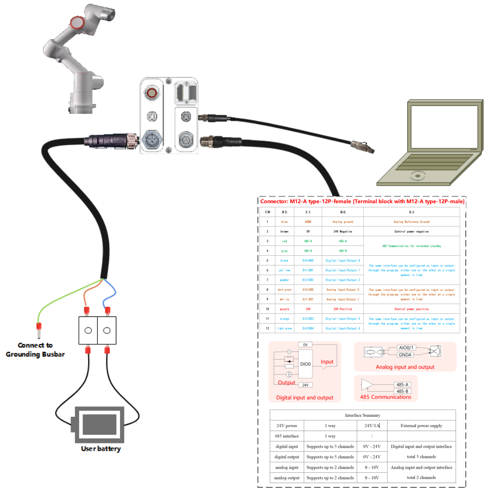
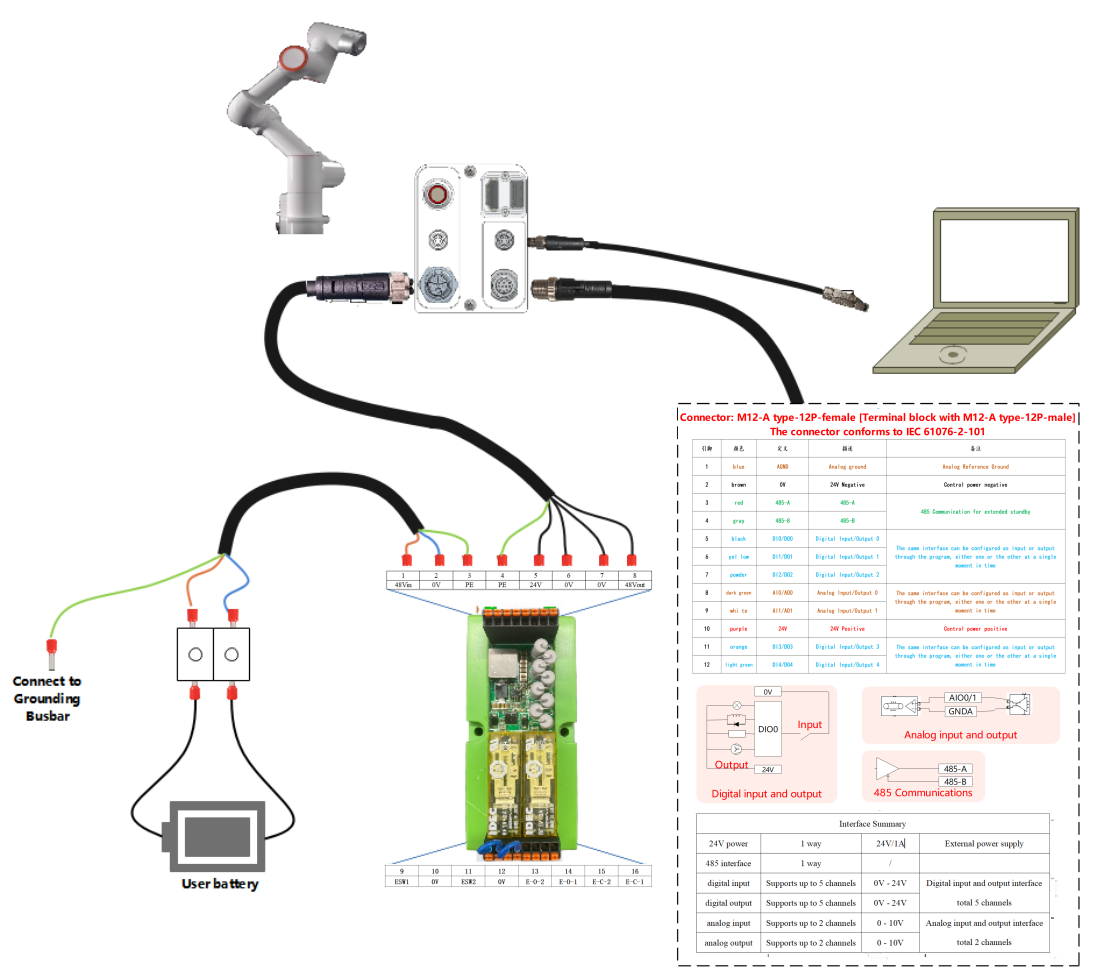
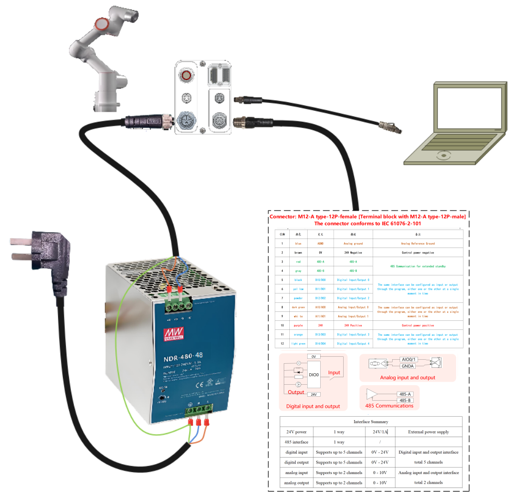
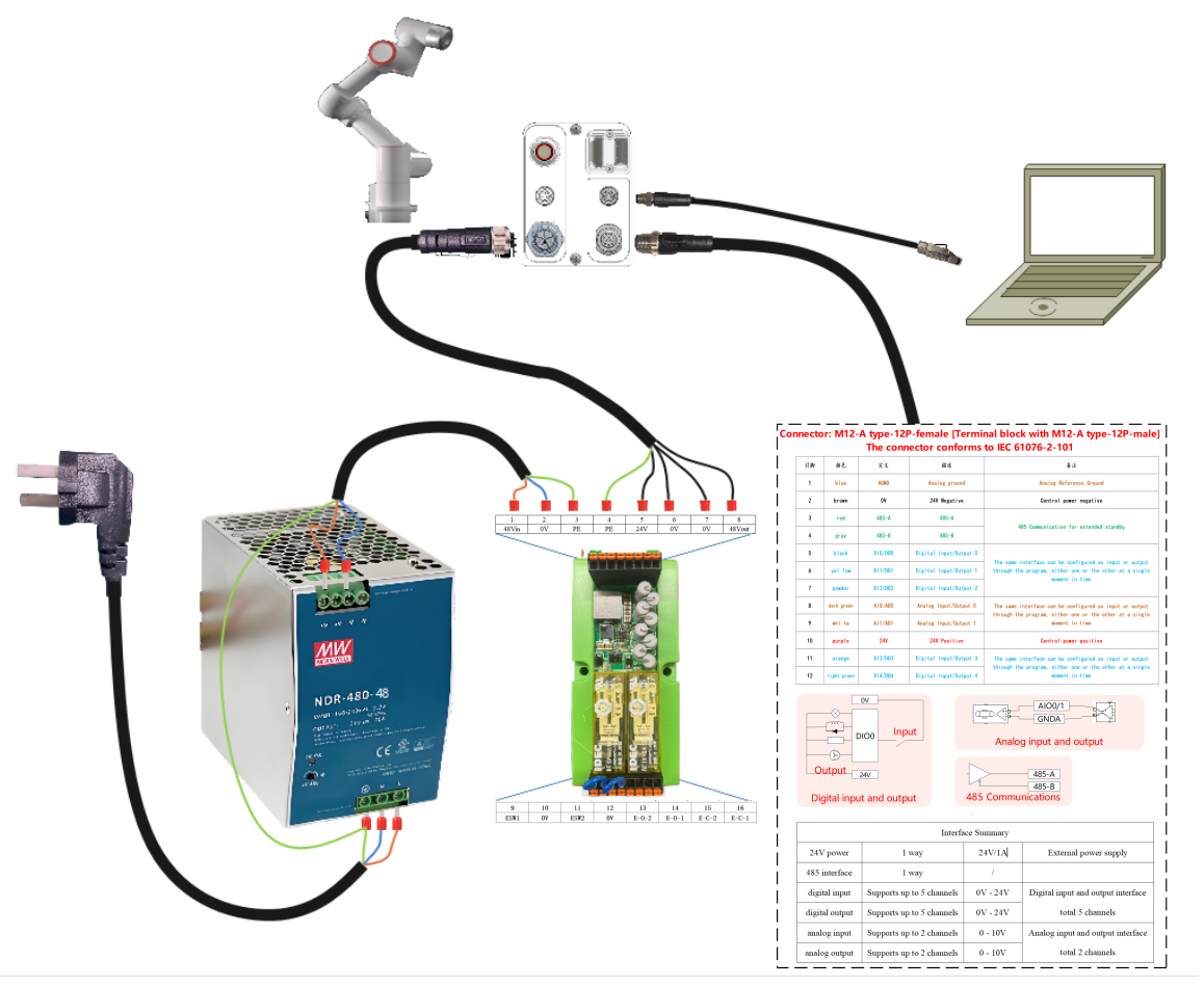
You can use the end -panel’s I/O and 485 communication interfaces to control various devices, including pneumatic relay, PLC and emergency stop buttons. The PIN foot distribution and its PIN foot explanation is shown in figure below. The I/O connector model is M12 connector 8 cores.
Note
End board I/O and 485 interfaces are prohibited from hot plugging.
Figure 3.5-5 The schematic diagram of the end version of the electrical interface
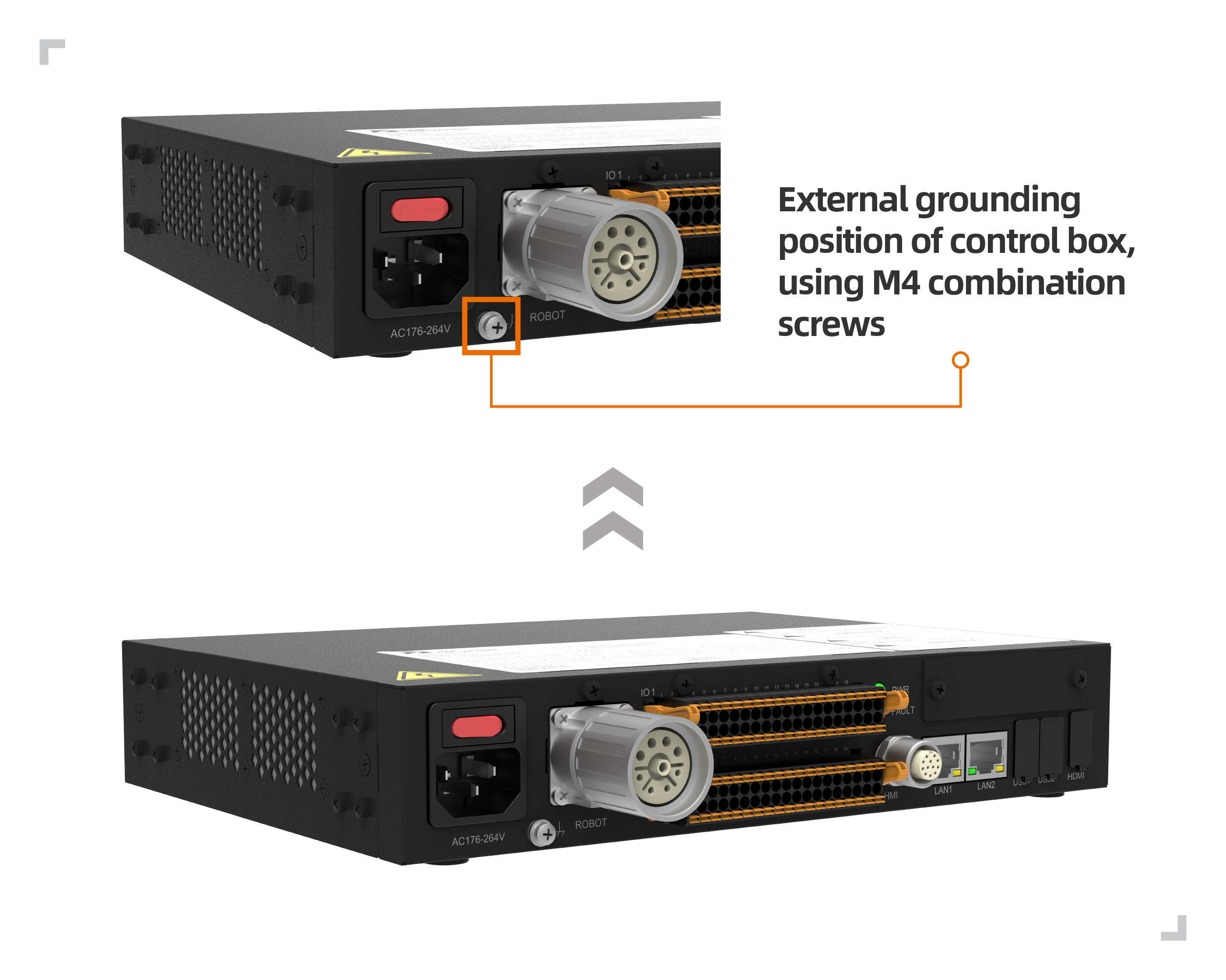
The control box is located at the M4 combination screw in the upper left of the power switch, as shown in figure below.
Figure 3.5-6 Demonstration diagram of the control box
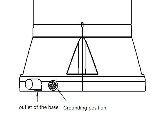
The body is located on the right side of the base of the base, as shown in figure below.
Figure 3.5-7 Dragon schematic diagram of the body
The protective wire used alone, the cross -sectional area should not be less than:
2.5mm2 copper or 16mm2 aluminum,if mechanical injury protection is provided (wire pipe, pipeline, etc.)
4mm2 copper or 16mm2 aluminum,if no mechanical damage protection is provided
3.5.6. The common specifications of all digital I/O
This section stipulates the electrical specifications of the following control box 24 volt digital input/output:
Safety I/O
Universal digital amount I/O
Robots must be installed in accordance with electrical specifications.
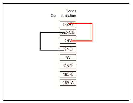
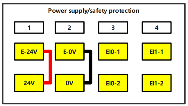
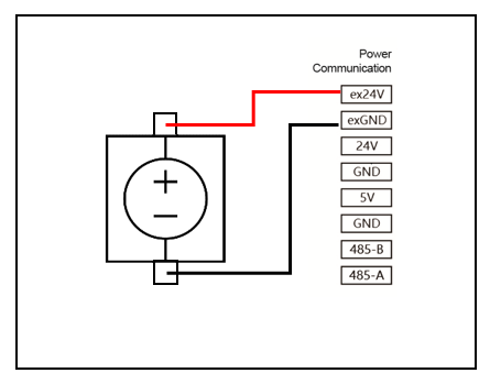
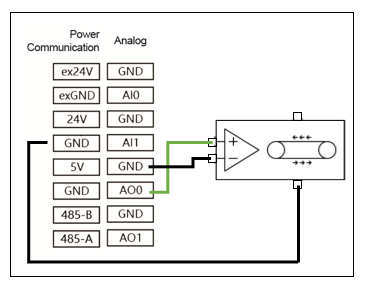
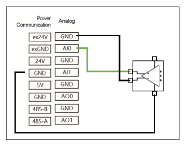
By configuring the “Power Communication” interface, you can use an internal or external 24V power supply to power the digital I/O. In this interface, the upper two terminals (ex24V and exon) are the 24V and ground of the external power supply, and the lower two terminals (24V and GND) are the 24V and ground of the internal power supply. The default configuration uses the internal power supply, as shown in the following figures for the control box and integrated mini control box (mini BOX).
Control Box
Integrated Mini Control Box (mini BOX)
Figure 3.5-8 Power Communication Schematic 01
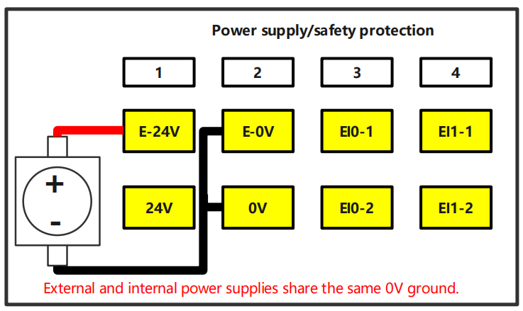
If the load power is high, connect an external power supply as shown in the figure below. For the AC wide voltage integrated mini control box (mini BOX), the external power supply and internal power supply share a common 0V connection.
Control Box
Integrated Mini Control Box (mini BOX)
Figure 3.5-9 Power Communication Schematic 02
The electrical specifications of internal and external power are shown in table below Internal and external electrical specifications:
Table 2.5‑1 Internal and external power supply electrical specifications
Terminal
Parameter
Mininum
Typical
Maximum
Unit
Internal 24V power supply
[ex24V -exGND]
[ex24V -exGND]
Voltage
Current
23
0
24
-
25
2
V
A
Internal 24V power supply
[24V- GND]
[24V- GND]
Voltage
Current
23
0
24
-
25
1.5
V
A
The electrical specifications of digital I/O are shown in table below Digital I/O Electric Specifications:
Table 2.5‑2 Digital I/O Electric Specification
Terminal
Parameter
Mininum
Typical
Maximum
Unit
Digital output
[COx/DOx]
[COx/DOx]
[COx/DOx]
Current
Pressure drop
Leakage current
0
0
0
-
-
-
1
0.5
0.1
A
V
mA
[COx/DOx]
function
-
NPN
-
Type
Digital output
[EIx/SIx/CIx/DIx]
[EIx/SIx/CIx/DIx]
[EIx/SIx/CIx/DIx]
OFF
ON
Current(11~30)
-3
11
2
-
-
-
5
30
15
V
V
mA
[EIx/SIx/CIx/DIx]
function
-
NPN
-
Type
The electrical specifications for digital DO loads are shown in the table below.
Table 3.5-3 Electrical Specifications for Single-Channel Digital DO Load
This section describes the electrical specifications of security I/O, and must abide by the general electrical specifications in Section 3.5.6.
Safety devices and equipment must be installed in accordance with the safety description and risk assessment, see section 3.1. All security I/O is paired (redundant) and must be stored as two independent branches. Single failures should not cause loss of security function.
Safety I/O includes emergency stop and security stop. Urgent stop input is only used for emergency stop equipment, and safely stops input for various security -related protection equipment. Functional differences are shown in table below:
Table 2.5-3 Functional difference
Emergency stop
Safe stop
Robot stops moving
Yes
Yes
Stop Category
Category 0
Category 1
Program execution
Stop
Pause
Robot power supply
Close
Open
Restart
Manual
Automatic or manual
Frequency of use
Infrequent
Often
Reinitialization required
Need
Needless
Warning
Do not connect the security signal to a PLC that does not have the correct and safe level. If this warning does not follow, it may cause serious damage or death because one of the security stop function may be covered. Security interface signals must be separated from normal I/O interface signals.
All I/O is a redundant -related I/O built (two independent channels). Two channels must be kept separately so that a single failure will not cause security function.
Before the robot is put into operation, it is necessary to verify the emergency stop safety function (the robot is powered on, press the emergency stop button, the robot is disconnected, the power is turned off, the rotating emergency stop button, the power is turned on, and the robot is re -power to enable it). Safety functions must be tested regularly.
Robot installation should comply with these specifications. Otherwise, it may lead to severe damage or death, because the safety stop function may be over.
The following sections are given some examples of how to use security I/O.
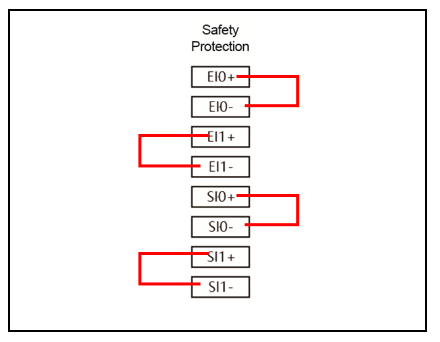
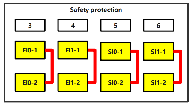
Default safety configuration
When the robot leaves the factory, it has the default configuration. It can be operated without any additional safety devices. Please refer to figure below.
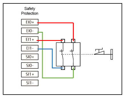
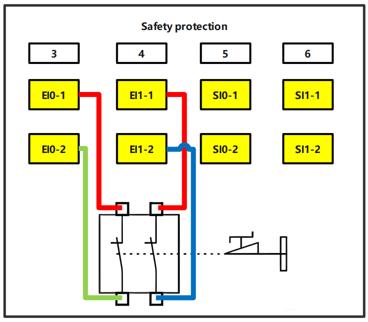
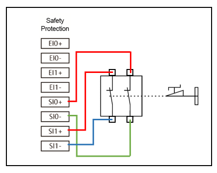
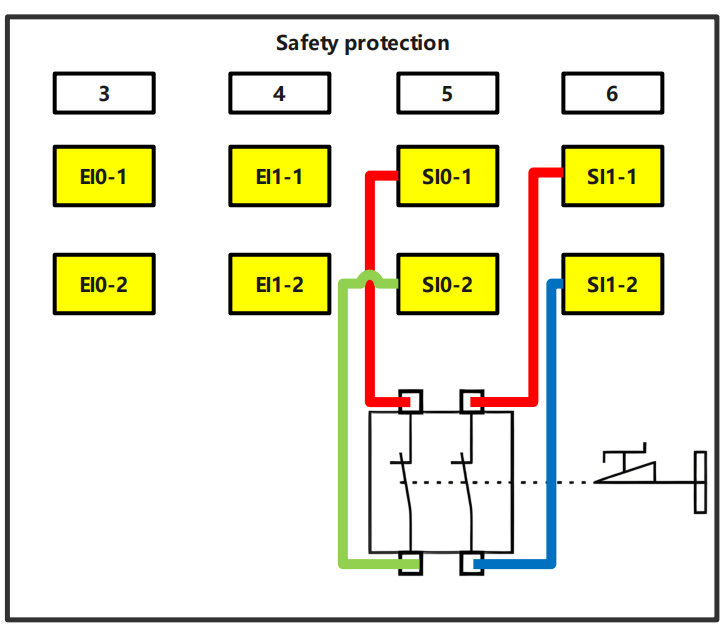
Connect the security stop button
An example of a safe stop device is the door switch that the robot stops when the door is turned on. Please refer to figure below.
This section describes the electrical specifications of the general digital I/O, and must abide by the general electrical specifications in Section 3.5.6.
The general digital amount I/O can be used to drive relays, solenoid valves and other devices or interact with other PLCs.
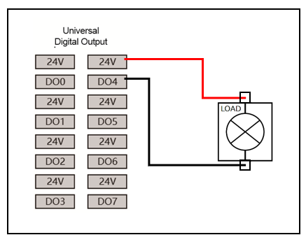
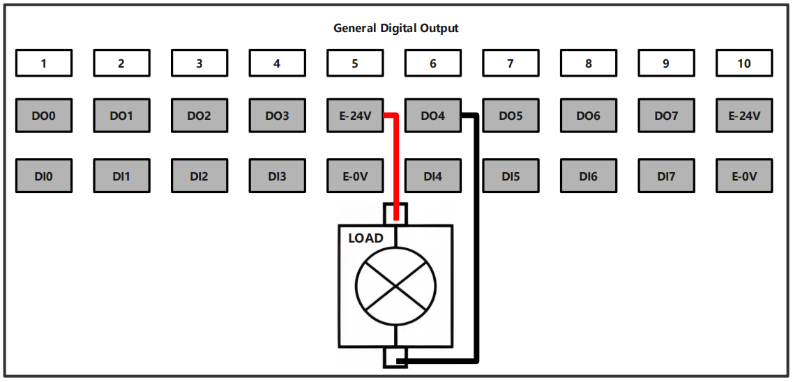
Digital quantity output control load
This example demonstrates how to connect the digital quantity output to control the load, Please refer to figure below.
Control Box
Integrated Mini Control Box (mini BOX)
Figure 3.5-13 Great digital quantity output schematic diagram 01
The definition of collaborative robots complies with international ISO standards and national regulations to ensure operator safety. We do not recommend directly applying the robot body in scenarios where the operation target is the human body. However, if the robot user or developer has a specific need to involve human targets, they must conduct thorough evaluations and ensure personnel safety by configuring a reliable, fully tested, and certified safety protection system for the robot body.
This manual serves only as a safety certification guide for customers. Maintenance operators must possess professional expertise. FaRo (法奥) assumes no responsibility for any incidents caused by non-professionals.
Important
If the robot (robot body, power module, or extension module) is damaged, altered, or modified due to human factors, FaRo refuses to bear any responsibility. FaRo is not liable for any damage caused to the robot or other equipment due to programming errors made by the customer.
The information in this manual does not cover the design, installation, or operation of a complete robot application, nor does it account for all peripheral devices that may affect the safety of the system. The design and installation of the complete system must comply with the safety requirements established by the standards and regulations of the country where the robot is installed.
FAIRINO integrators are responsible for ensuring compliance with relevant national laws and regulations, guaranteeing that the complete robot application poses no significant hazards. This includes but is not limited to:
Conducting a risk assessment for the complete robot system
Connecting additional mechanical and safety devices as defined in the risk assessment
Establishing appropriate safety settings in the software
Ensuring users do not modify any safety measures
Verifying the correct design and installation of the entire robot system
Providing clear usage instructions
Marking the integrator’s logo and contact information on the robot
Collecting all documentation, including this manual, in the technical file
The safety information in this manual does not constitute a general safety guarantee for robots. Even if all safety instructions are followed, personnel injury or equipment damage may still occur.
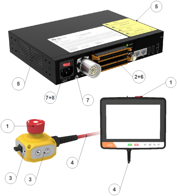
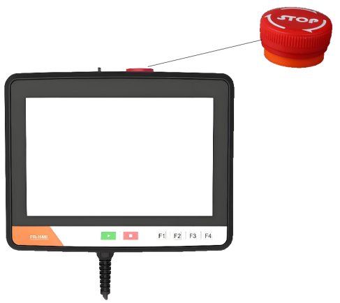
The robotic teaching pendant can use a computer or tablet to access and control the robot. The connection method can refer to Section 3.5.3 to explain. In addition, users can also use our FR-HMI osteter.