10. Palletizing FRCap
10.1. Palletizing FRCap plug-in package management
In the collaborative robot WebApp, “System Settings - FRCap Config.” page,click the “Import” button and select the palletizing FRCap plug-in package (name format: plug-in package name + version number. frcap, example: palletizer Palletizer-v0.0.0.plugin) to upload. After the upload is successful, the list displays the successfully imported palletized FRCap plug-in package, including Status, Name, Version, Description and Author, etc. The palletizing FRCap plug-in package can be “Deactivate”, “Enabled” and “Delete” in the operation bar.
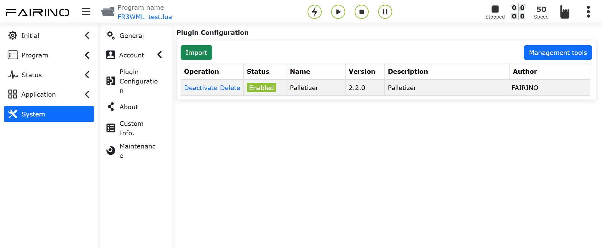
Figure 10-1-1 WebApp plug-in configuration interface
After successfully importing the palletizing FRCap plug-in package for the first time, the status of the plug-in package is “Disabled”. Click the “Enable” button. After successful activation, the “Auxiliary Application” module of the collaborative robot WebApp adds the palletizing FRCap plug-in package start page ( For example: the page module name corresponding to Palletizer-v0.0.0.plugin is “Palletizer”). Click the “Start” button to enter the homepage, view the currently configured palletizing formula, and use it according to your needs.
Note
If the recipe is empty, please add/import the recipe first.
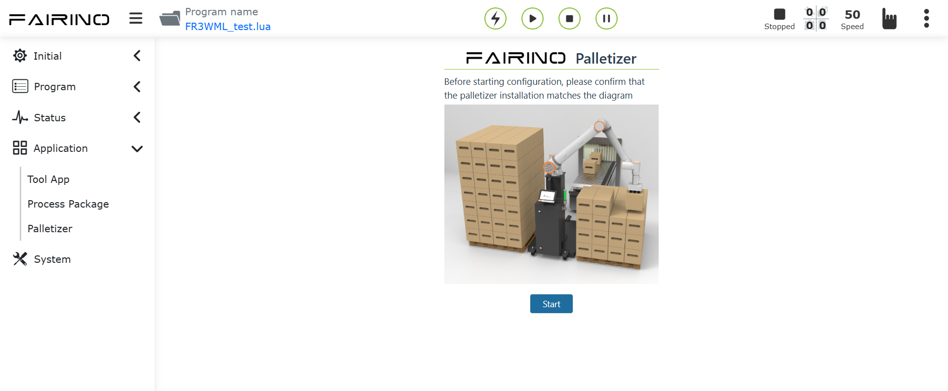
Figure 10-1-2 WebApp+ palletizing FRCap display diagram
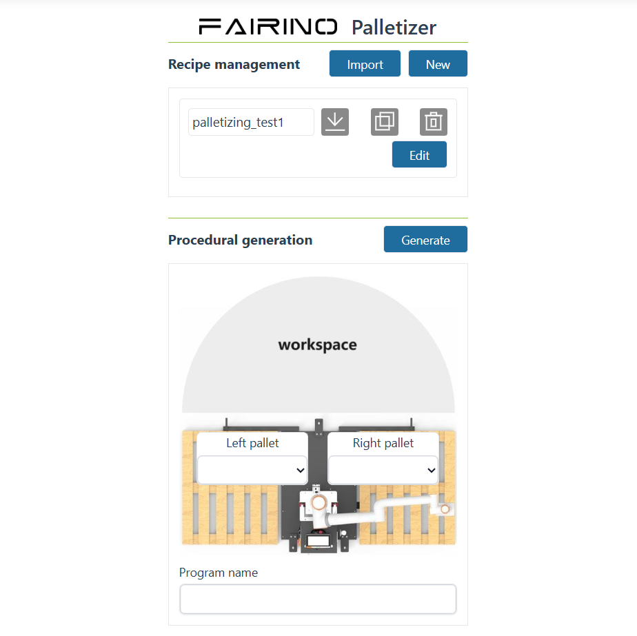
Figure 10-1-3 Palletizing FRCap Home Page
10.2. Recipe management
Each recipe is divided into three major areas: recipe name, recipe operation and recipe editing. The operation area buttons are: Rename, Export, Copy and Delete.
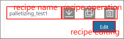
Figure 10-2-1 Recipe area division
Note

Note

Note

10.2.1. Obtain
After entering the homepage of the palletizing plug-in package, you can obtain all current recipes. When the number of recipes is greater than four, a scroll bar appears in the recipe display area, and the user can scroll up and down to view the recipes.
Note
All recipe names start with “palletizing”, for example “palletizing_test1”.
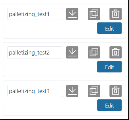
Figure 10-2-2 Recipe acquisition
10.2.2. New
In the operation area of any formula, click the “Add” button to enter the “New Formula” pop-up window, enter the name of the palletizing formula, and click the “Confirm” button. After the addition is successful, the new palletizing formula will be added to the formula display area.
Note
All recipe names start with “palletizing”. There is no need to enter “palletizing”. You only need to enter the name after “_”. For example, “palletizing_add”, enter “add”.
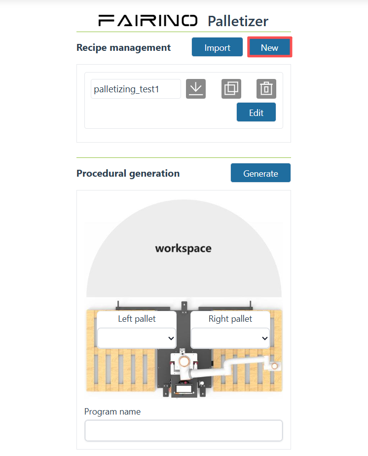
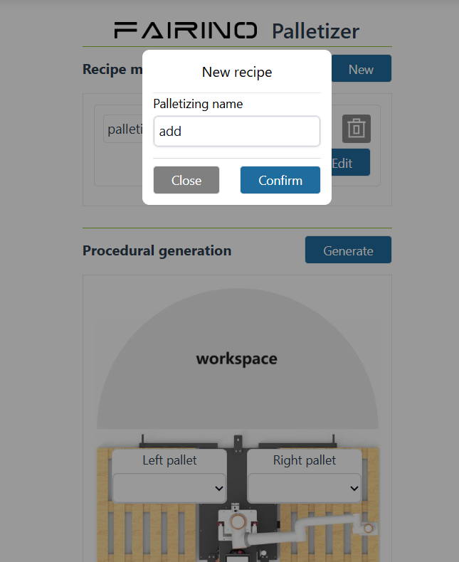
Figure 10-2-3 New recipe added
10.2.3. Rename
In the operation area of any formula, click the “Rename” icon to enter the “Palletizing Recipe Rename” pop-up window, enter the name of the palletizing formula, and click the “Confirm” button. After the renaming is successful, the original palletizing recipe name in the recipe display area is renamed.
Note
All recipe names start with “palletizing”. There is no need to enter “palletizing”. The modal window will automatically bring out the name after “_”. For example, “palletizing_rename” will automatically bring out “rename”.
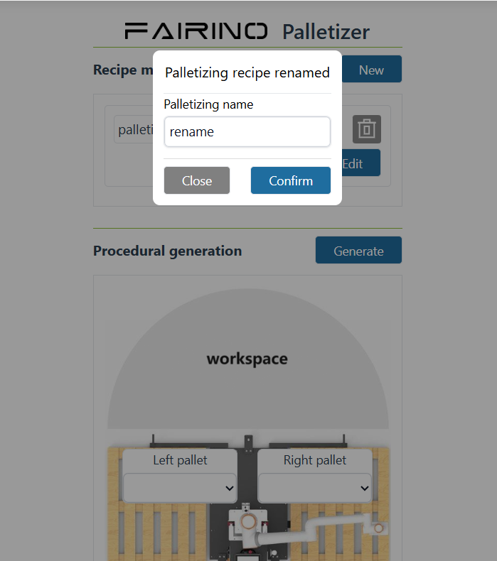
Figure 10-2-4 Recipe rename
10.2.4. Export
In the operation area of any recipe, click the “Export” icon to download all data of the current recipe.
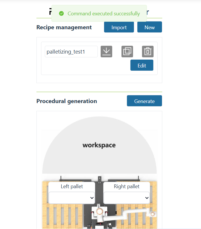
Figure 10-2-5 Recipe export
10.2.5. Copy
In the operation area of any formula, click the “Copy” icon to enter the “Palletizing Formula Copy” pop-up window, enter the name of the palletizing formula, and click the “Confirm” button. After the copy is successful, the copied palletizing formula will be added to the formula display area.
Note
All recipe names start with “palletizing”. There is no need to enter “palletizing”. The modal window will automatically bring out the names after “_”. For example, “palletizing_copy” will automatically bring out “copy”.
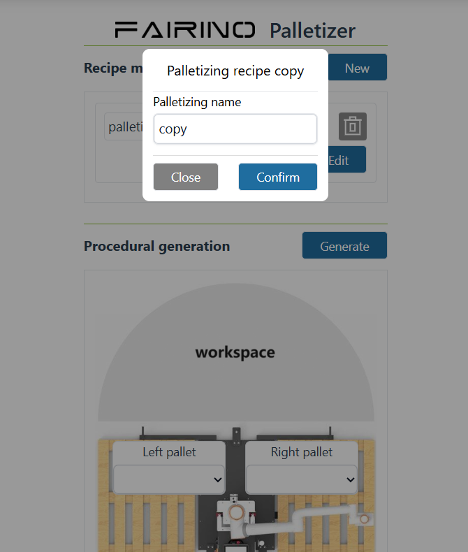
Figure 10-2-6 Recipe copy
10.2.6. Delete
In the operation area of any recipe, click the “Delete” icon to delete the current recipe.
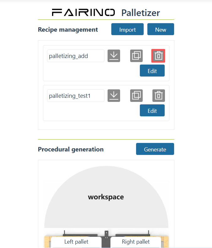
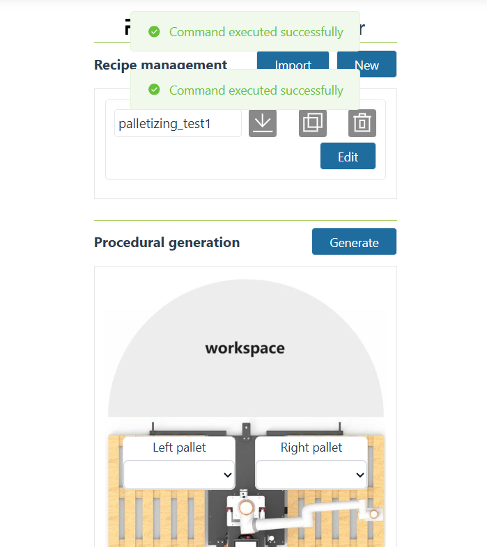
Figure 10-2-7 Recipe delete
10.2.7. Edit
For any recipe, click the “Edit” button to enter the configuration interface of the current recipe.
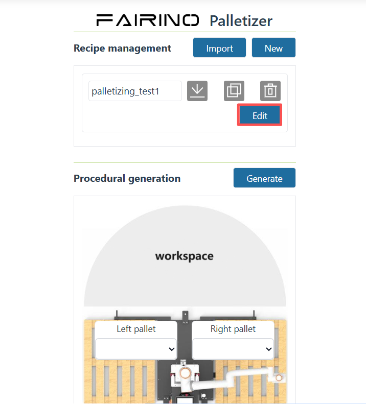
Figure 10-2-8 Palletizing recipe editor
10.2.8. Import
Click the “Import” button, select the compressed package of the palletizing formula and upload it. After the import is successful, the imported formula will be added to the palletizing formula.
Note
All recipe compressed package names start with “palletizing” and end with “.tar.gz”, such as “palletizing_import.tar.gz”.
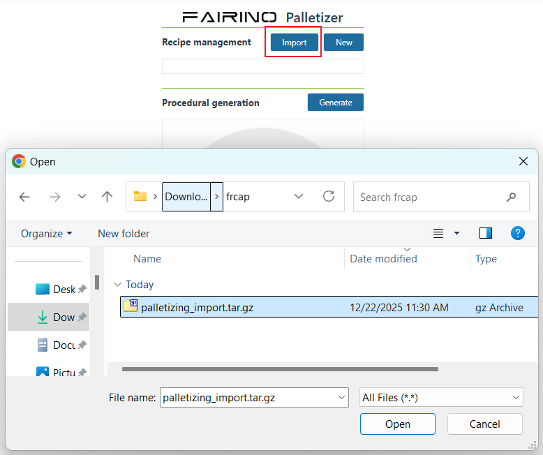
Figure 10-2-9 Recipe import
Important
When “adding”, “renaming” and “copying” a palletizing formula, entering an existing formula name will prompt “There is already a formula with the same name”.
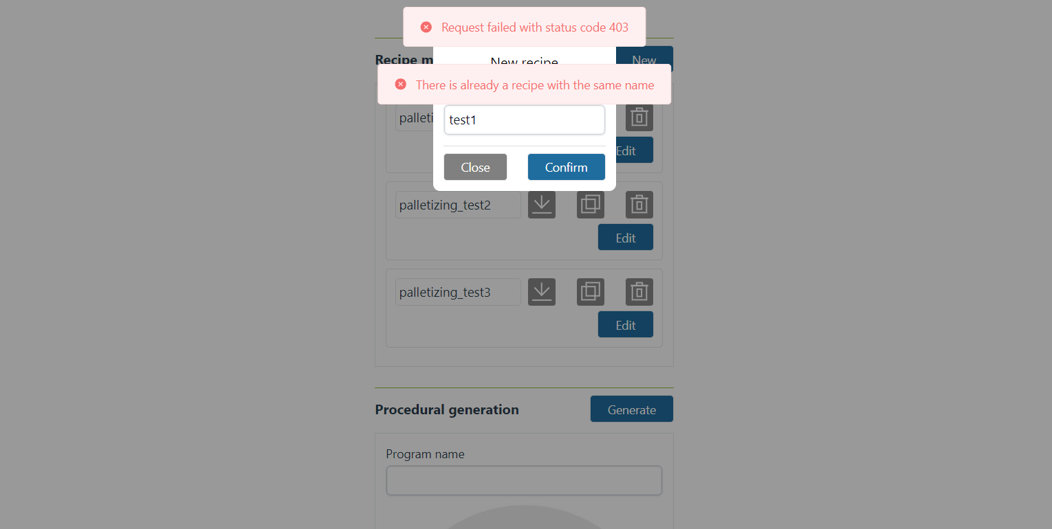
Figure 10-2-10 Tips for recipes with the same name
10.3. Recipe configuration
The configuration interface of any recipe displays the basic information of boxes, trays, modes and advanced configurations, and configures specific parameters in the corresponding configuration column.
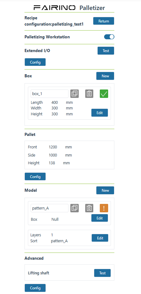
Figure 10-3-1 Palletizing recipe editing interface
10.3.1. Workstation Settings
In recipe editing, you can choose whether to use a palletizing workstation, as shown in Figure 2-2. If a palletizing workstation is used, the corresponding palletizing functions will be completed using I/O signals from the workstation PLC; if no palletizing workstation is selected, the palletizing functions will default to using I/O signals from the control box.
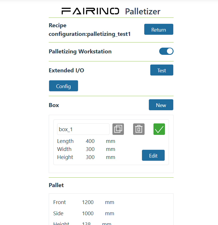
Figure 10-3-1-1 Recipe Editing Page
10.3.2. Palletizing Function I/O Wiring Configuration
After selecting to use a palletizing workstation, click on Extended I/O Configuration. Based on the corresponding functions and the actual wiring of the I/O interfaces with the PLC, you can customize the selection of I/O signal configuration for palletizing functions. Figure shows the default wiring configuration for the palletizing workstation.
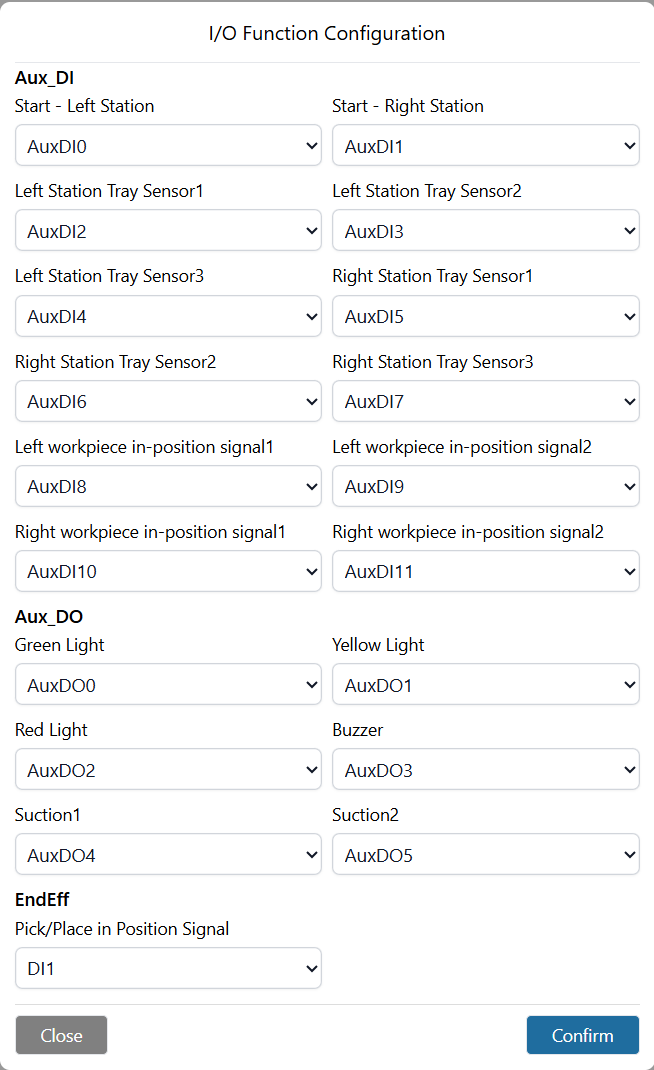
Figure 10-3-1-2 Default Wiring Configuration for Palletizing Workstation
If you choose not to use a palletizing workstation, the system defaults to using control box I/O signals. Based on the corresponding functions and the actual wiring of the I/O interfaces with the control box, you can customize the selection of I/O signal configuration for palletizing functions. Figure shows the default wiring configuration when no palletizing workstation is used (using control box I/O).
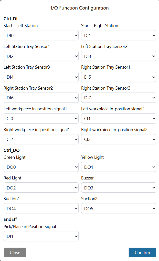
Figure 10-3-1-3 Default Wiring Configuration for No Palletizing Workstation (Control Box I/O)
10.3.3. Palletizing Function I/O Communication Test
When using a palletizing workstation, after configuring the extended I/O signals for the workstation palletizing workstation, you can click “Test” to verify the functionality of the wired I/O;
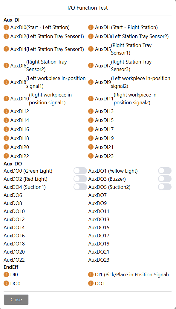
Figure 10-3-1-4 Palletizing Workstation I/O Wiring Test
When no palletizing workstation is selected, after configuring the control box I/O signals corresponding to the palletizing functions, you can click “Test” to verify the functionality of the wired I/O;
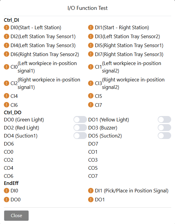
Figure 10-3-1-5 No Palletizing Workstation (Control Box I/O) Wiring Test
10.3.4. Box operation
Boxes can be configured with multiple boxes of different types.
Click the “Add” button. After the addition is successful, a new box will be added in the current order.
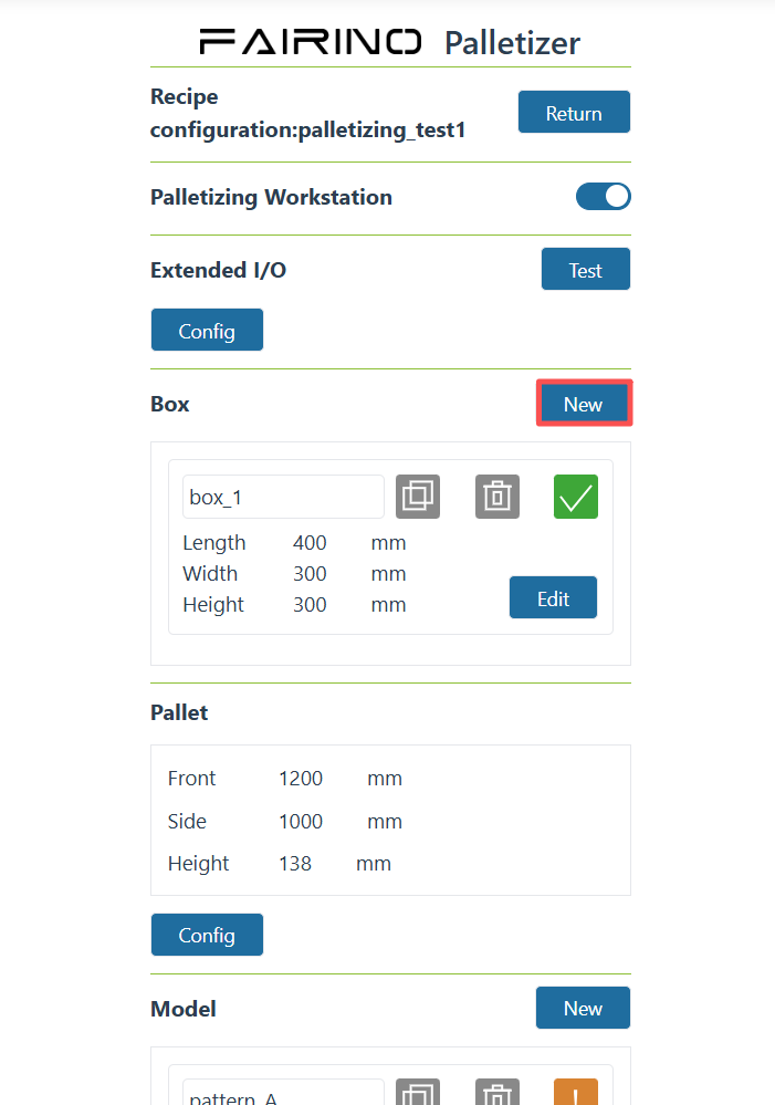
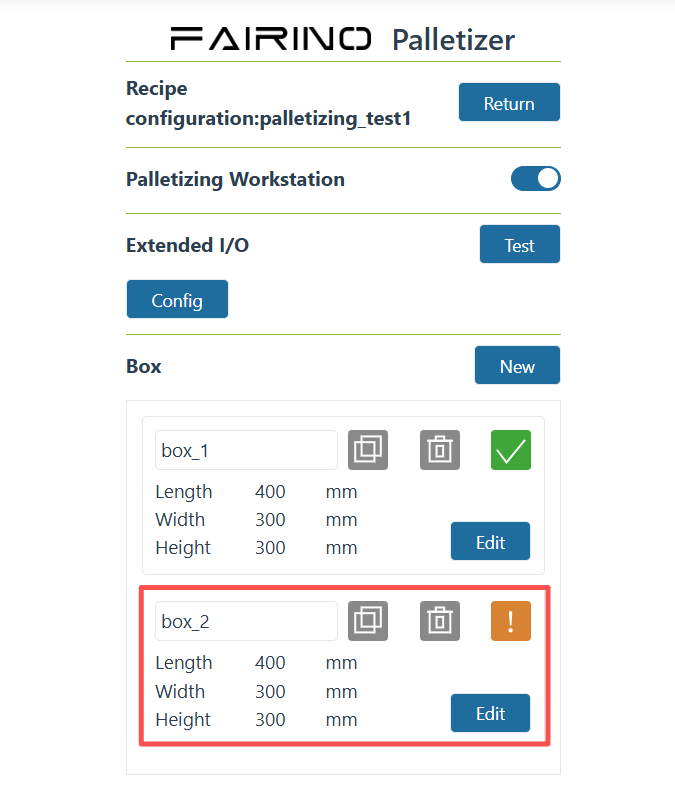
Figure 10-3-2 Add new box
Click the input box area where the box name is displayed, and the “Box Rename” modal window will pop up. After entering the name, click the “Confirm” button to confirm the renaming.
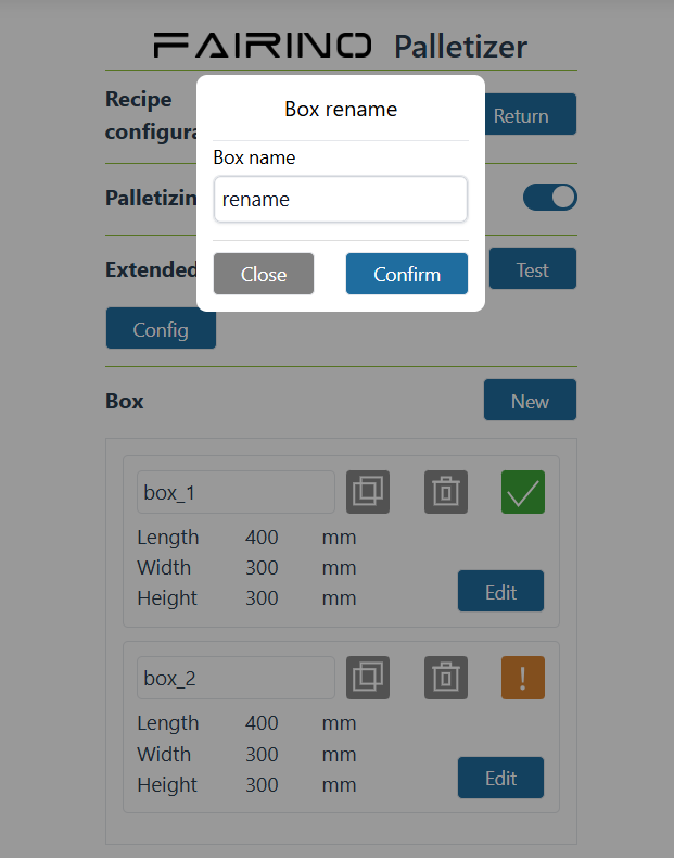
Figure 10-3-3 Rename box
Click the “Copy” icon. After the copy is successful, copy a box based on the current box name.

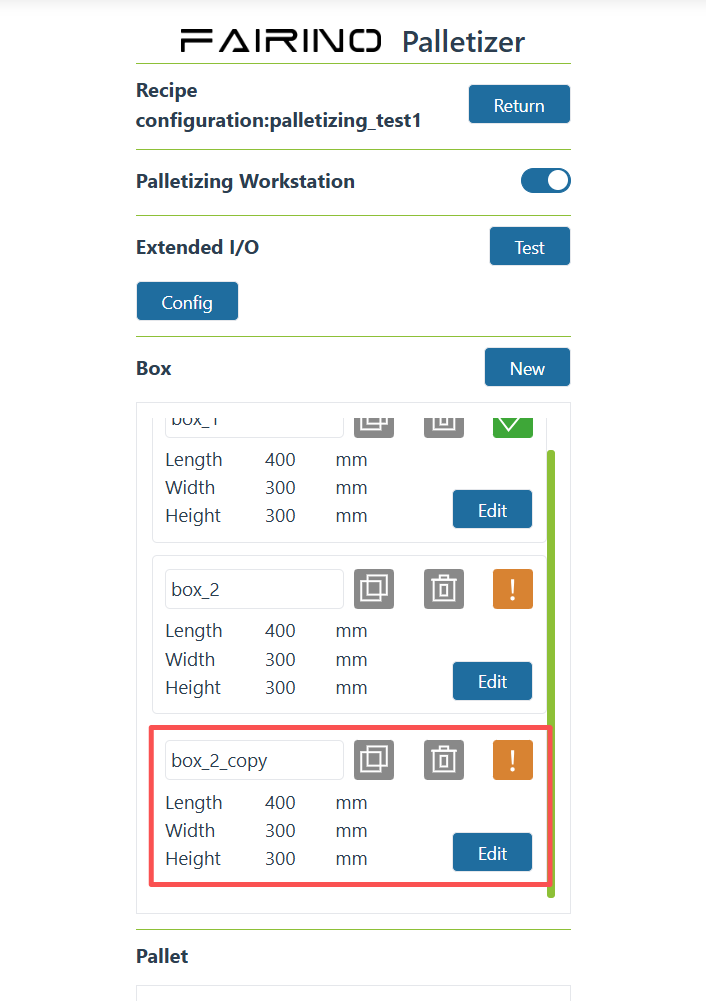
Figure 10-3-4 Copy box
Click the “Delete” icon to delete the box data.
Note
Do not delete boxes that have been configured in the mode configuration.
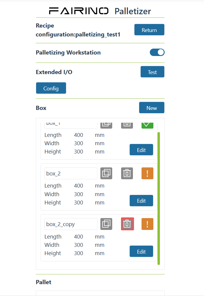
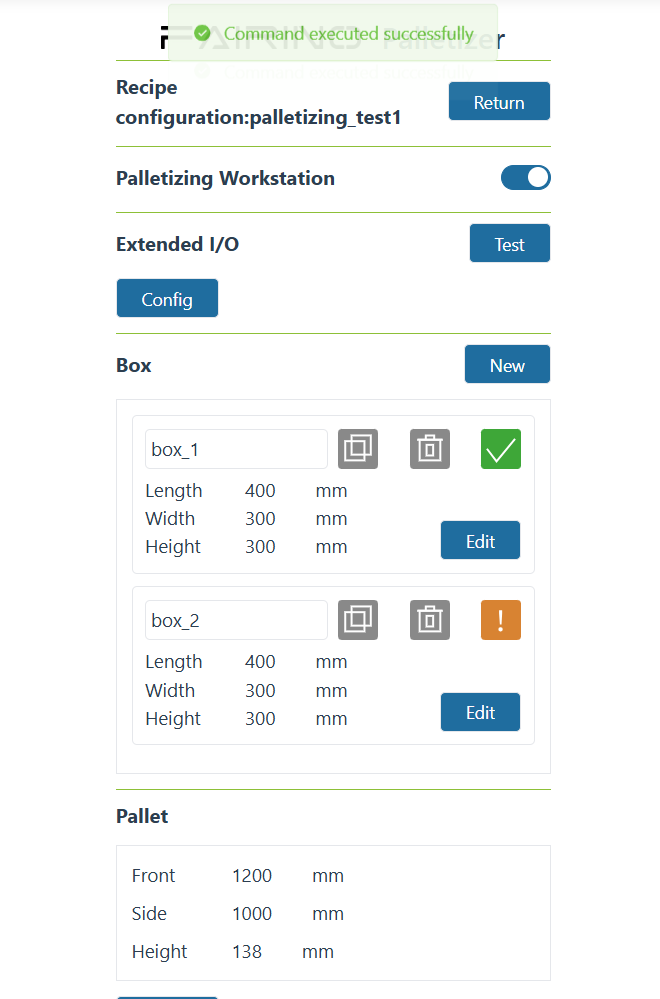
Figure 10-3-5 Delete box
For any box, click the “Edit” button to enter the box parameter configuration interface. After the configuration is successful, the box configuration status chart is green; when the configuration is not completed, the box configuration status icon is yellow.
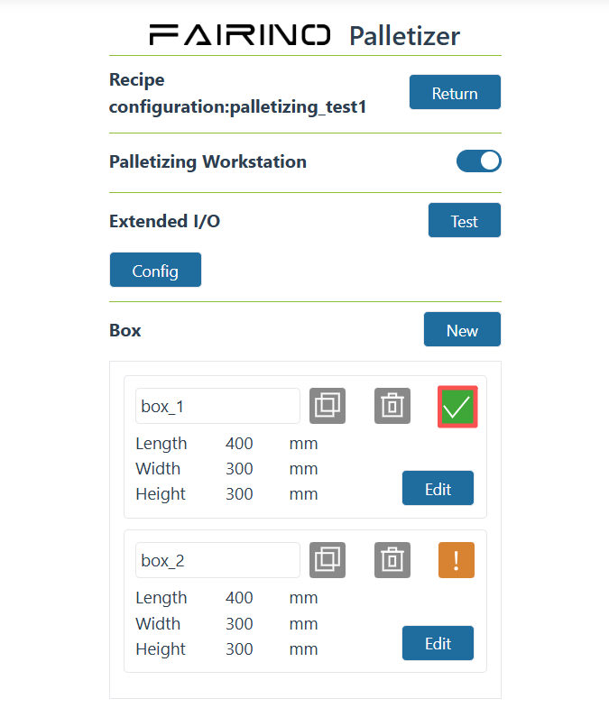
Figure 10-3-6 Box parameter configuration completed
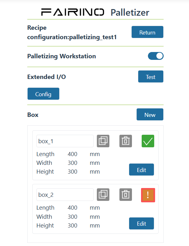
Figure 10-3-7 Box parameter configuration is not completed
10.3.5. Box parameters
Note

Note

Click “Edit” in the box configuration column to enter the “Box Configuration” pop-up window, set the “length”, “width”, “height”, “load” and “workpiece label orientation”, click “Confirm” button to complete the box information configuration; set the grab point of the box (keep the grab point at the center of the box, and the bottom of the suction cup will be in a squeeze state when in contact with the box), and click the “Record” button to complete the setting.
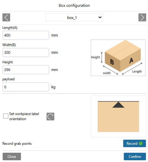
Figure 10-3-8 Box configuration
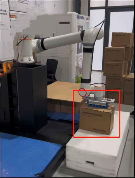
Figure 10-3-9 Box grab point
Important
The box grab point must be recorded, otherwise the length, width and height of the box cannot be configured.
10.3.6. Pallet configuration
Click “Config” in the pallet configuration column to enter the “Pallet Configuration” pop-up window, set the “front”, “side” and “height” of the pallet, then set the workstation transition point, and click “Confirm Configuration” to complete the pallet information setting.
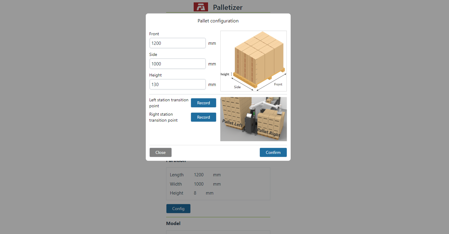
Figure 10-3-10 Pallet configuration
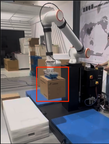
Figure 10-3-11 Left station transition point
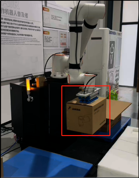
Figure 10-3-12 Right station transition point
Important
Station transition points must be recorded, otherwise the program that cannot be generated cannot be saved.
10.3.6.1. Pattern configuration
10.3.7. Pattern operation
When selecting boxes in a pattern configuration, you can select boxes of the same height but different lengths and widths. The mode display area is divided into: mode addition (configuring palletizing type) and palletizing layer configuration.
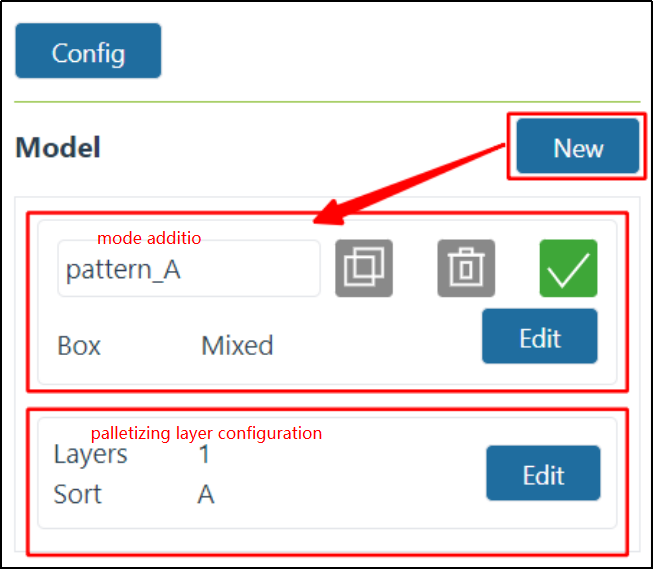
Figure 10-3-13 Mode display area
Click the “Add” button. After the addition is successful, a new mode will be added in the current order.
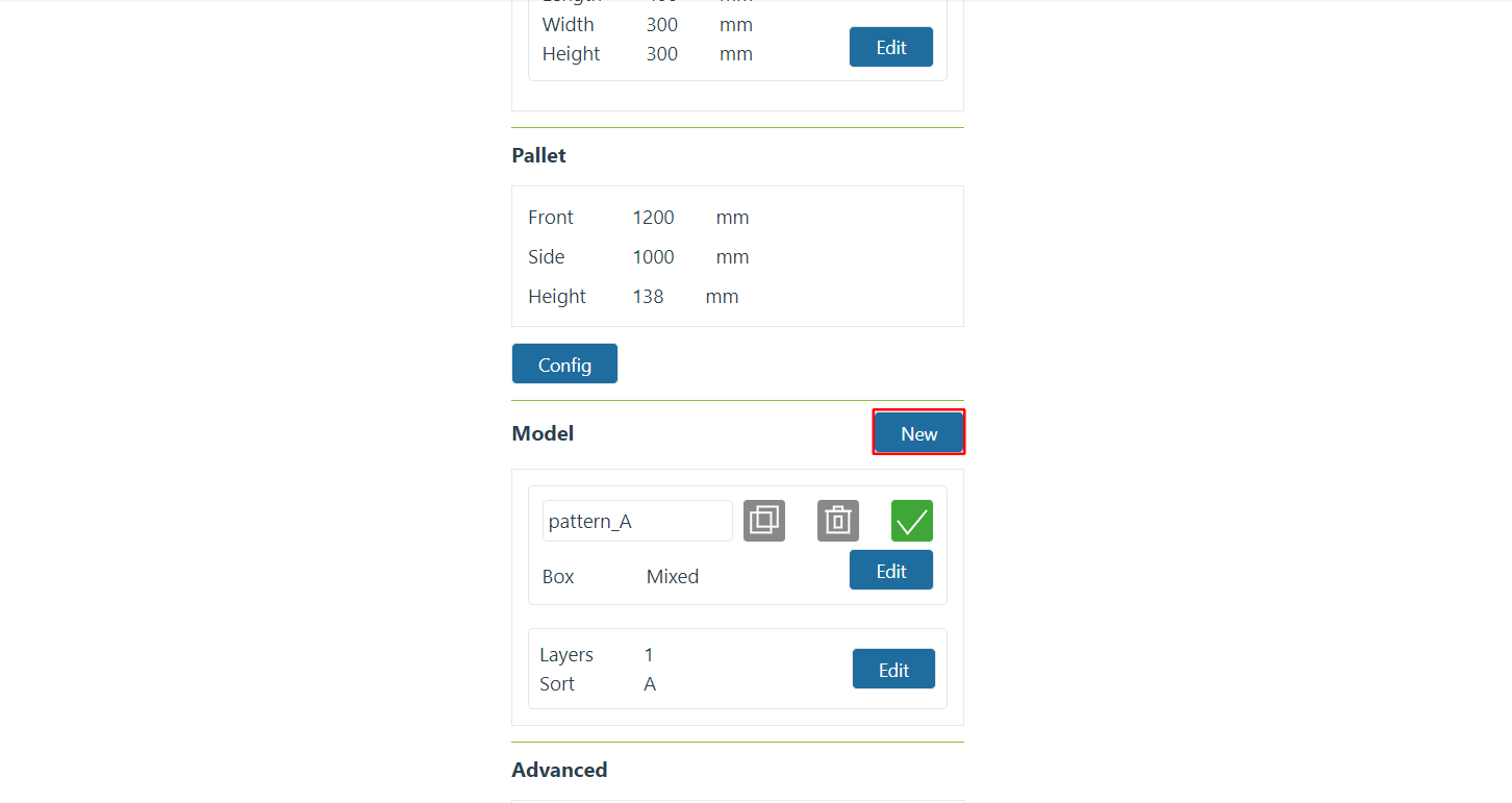
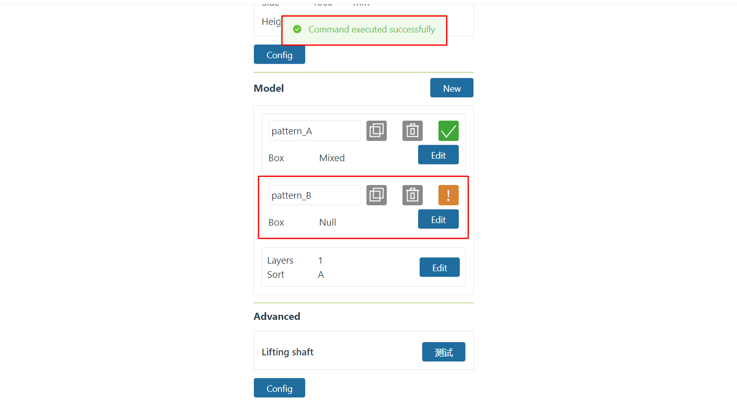
Figure 10-3-14 New pattern
In any mode in the mode adding area, click the input box area where the mode name is displayed, and the “Mode Rename” modal window will pop up. After entering the name, click the “Confirm” button to confirm the renaming.
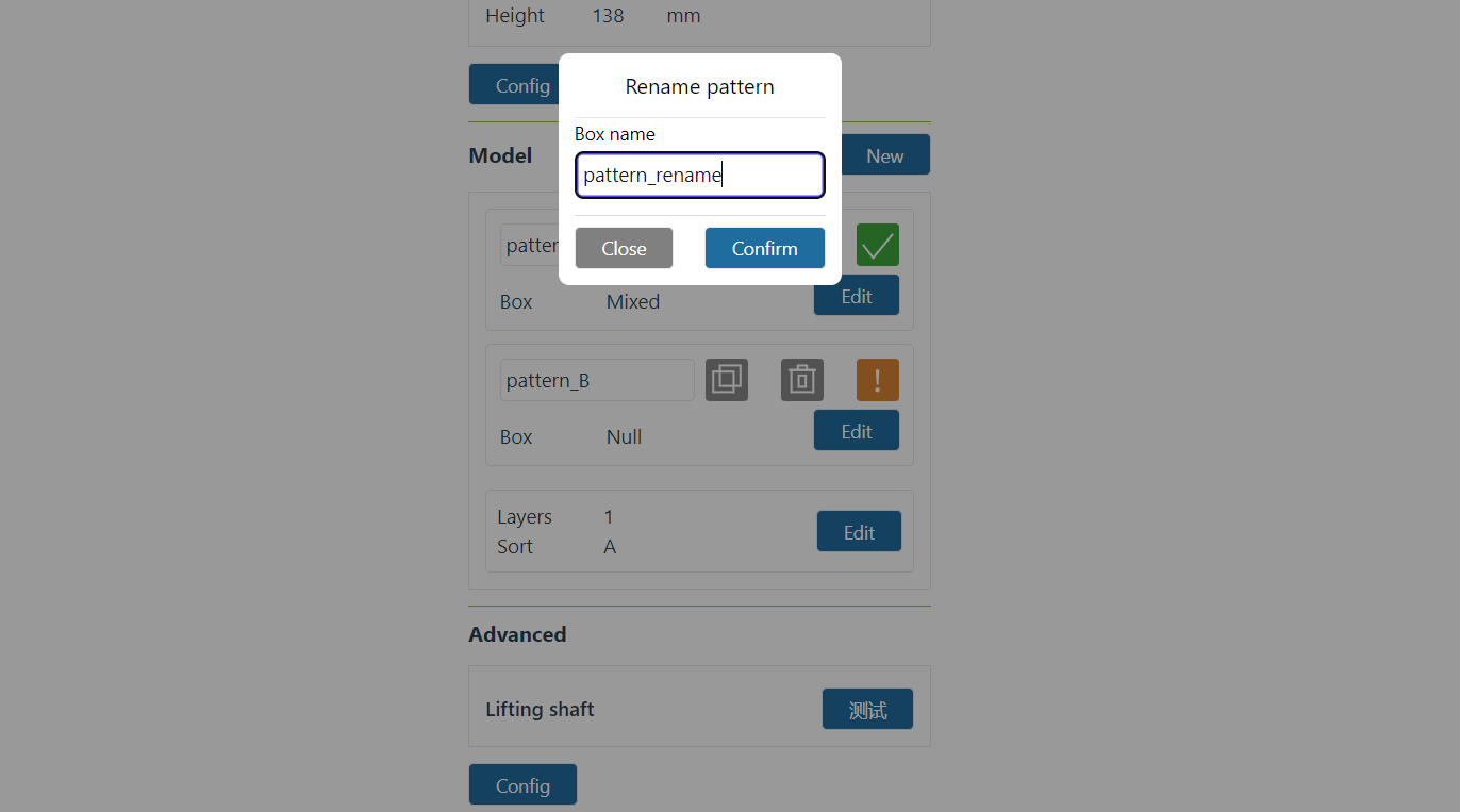
Figure 10-3-15 Rename pattern
In any mode in the mode adding area, click the “Copy” icon. After the copy is successful, a mode will be copied according to the current mode name.
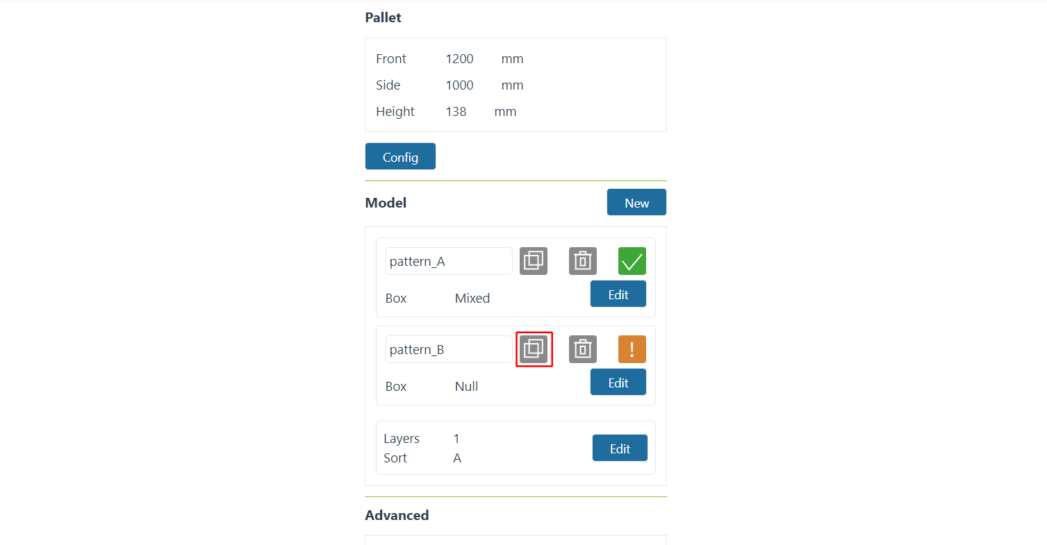
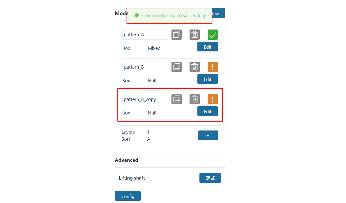
Figure 10-3-16 Copy pattern
In any mode in the mode adding area, click the “Delete” icon to delete the current mode data.

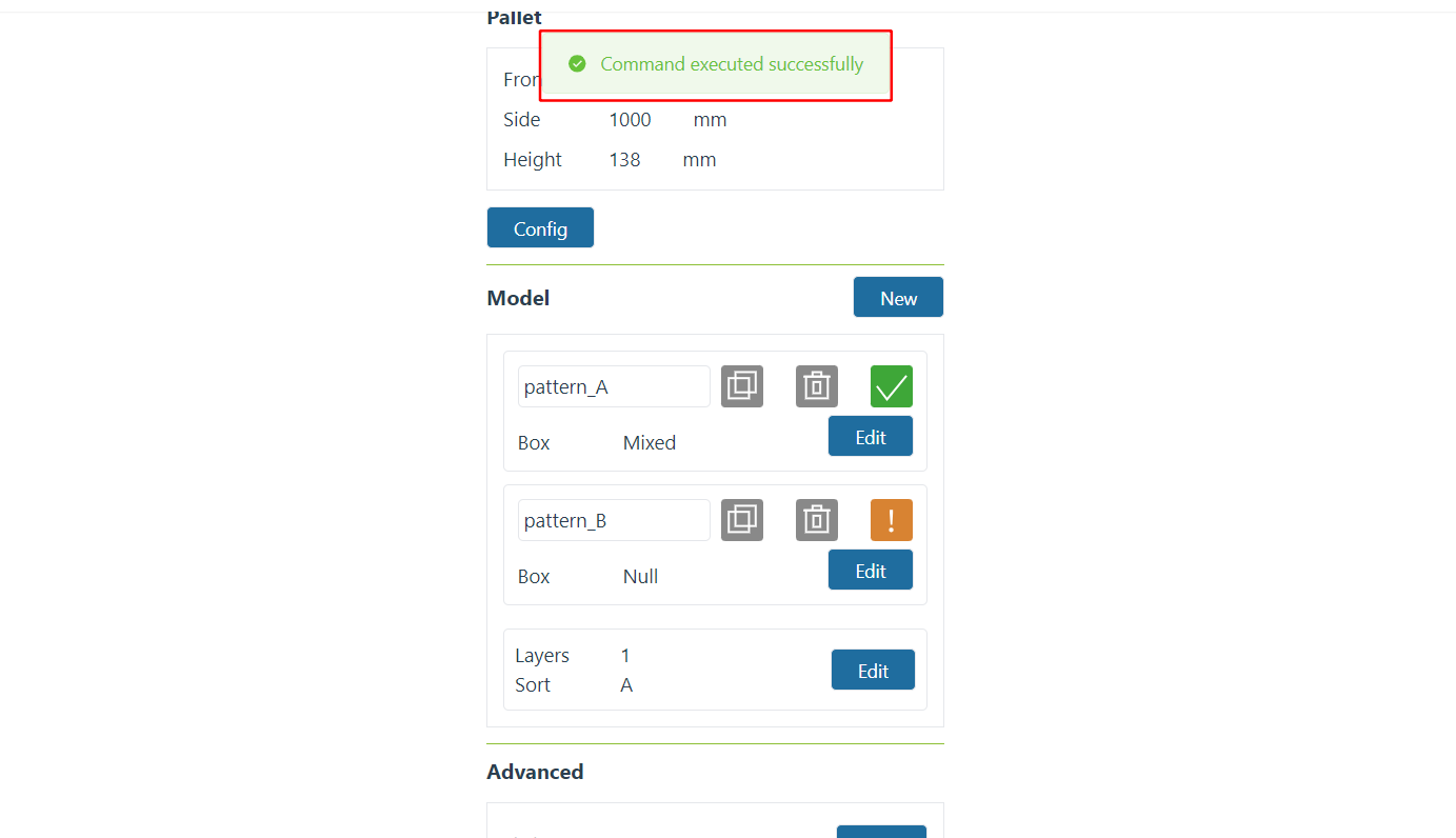
Figure 10-3-17 Delete pattern
In any mode in the mode adding area, click the “Edit” button to enter the “Mode Configuration” modal window and configure the palletizing type of the current mode. After the configuration is successful, the box configuration status chart is green; when the configuration is not completed, the box configuration status icon is yellow.
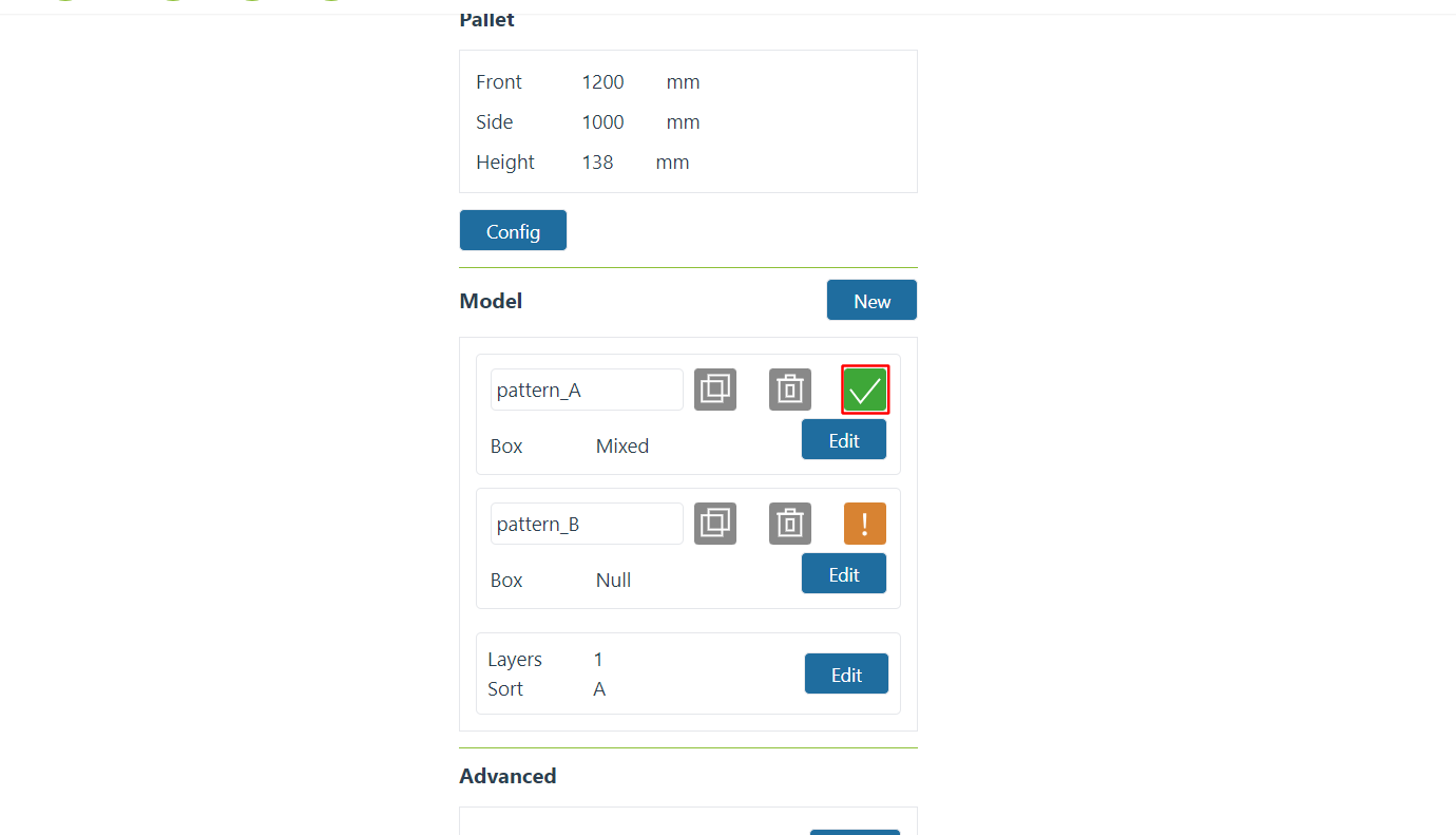
Figure 10-3-18 Pattern parameter configuration completed
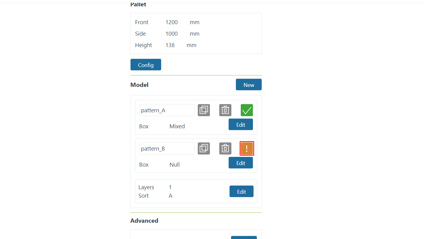
Figure 10-3-19 Mode parameter configuration is not completed
In the palletizing layer configuration area, the number and sorting of the palletizing layers are displayed. Click the “Edit” button to enter the “Palletizing Sequence Configuration” modal window, enter the “Number of Palletizing Layers”, select the mode of each layer, and click the “Confirm” button to complete the configuration.
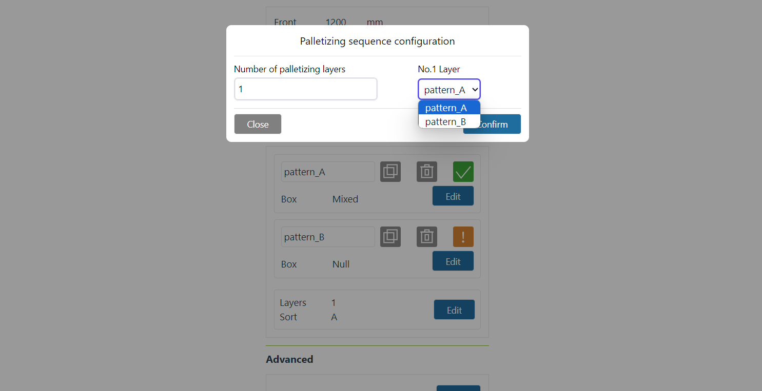
Figure 10-3-20 Palletizing layer configuration
10.3.8. Pattern parameters
Note
Note
Click “Edit” in the mode configuration column to enter the “Mode Configuration” pop-up window. It is mainly divided into three areas: pattern selection, box operation and stacking simulation.
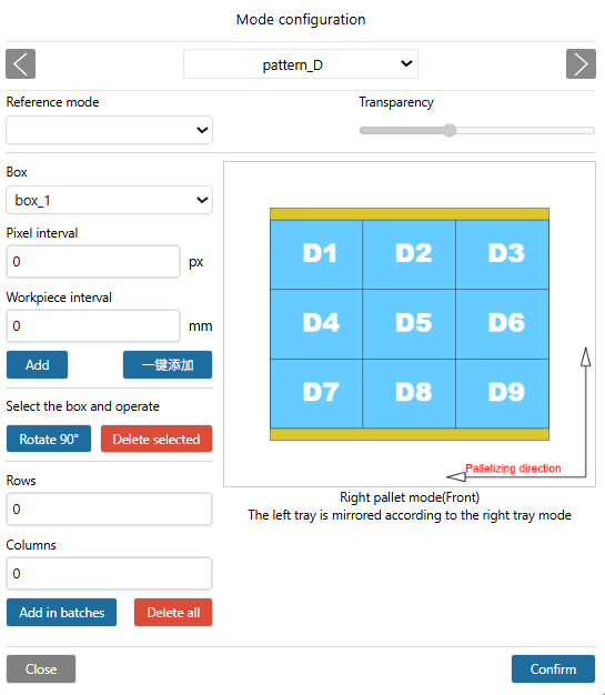
Figure 10-3-21 Pattern configuration
Important
When adding boxes, the background color of the workpiece turns red when there is a collision between boxes, and the above operation cannot be performed at this time. If necessary, please adjust the box to be collision-free.
In the pop-up header, select a mode, then choose boxes in the box operation area to add them under this mode. You can choose one-click addition, which by default fills the centered pallet with boxes without any gaps. Customize box spacing; boxes can be added individually or in batches. Click “Confirm” to complete the mode information setup. When the selected boxes have inconsistent heights, configuration cannot be completed, and the prompt “Box type heights are inconsistent and cannot be added to the same mode” will appear.
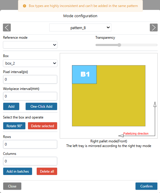
Figure 10-3-22 Tips for inconsistent heights of selected boxes
Select the reference mode (the selected mode cannot be selected), compare and see whether the current mode configuration can be palletized based on the reference mode, so that customers can intuitively check the box stacking types in different modes.
Note
Currently only two modes, A and B, are supported.
Important
Palletizing direction: Taking the right pallet as an example, the lower right corner is the farthest point. Place a row of workpieces vertically or horizontally from the lower right corner, then place workpieces horizontally or vertically in the upper row, and so on (Web page The palletizing direction has been marked, please check carefully). The left pallet places workpieces mirroring the right pallet mode.
10.3.8.1. Advanced configuration
Click “Config” in the advanced configuration column to enter the “Advanced Configuration” pop-up window. The configuration items are as follows:
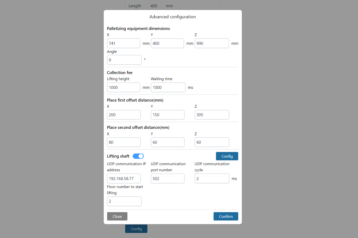
Figure 10-3-23 Advanced configuration
Dimensions of palletizing equipment: Dimensions of palletizing workbench.
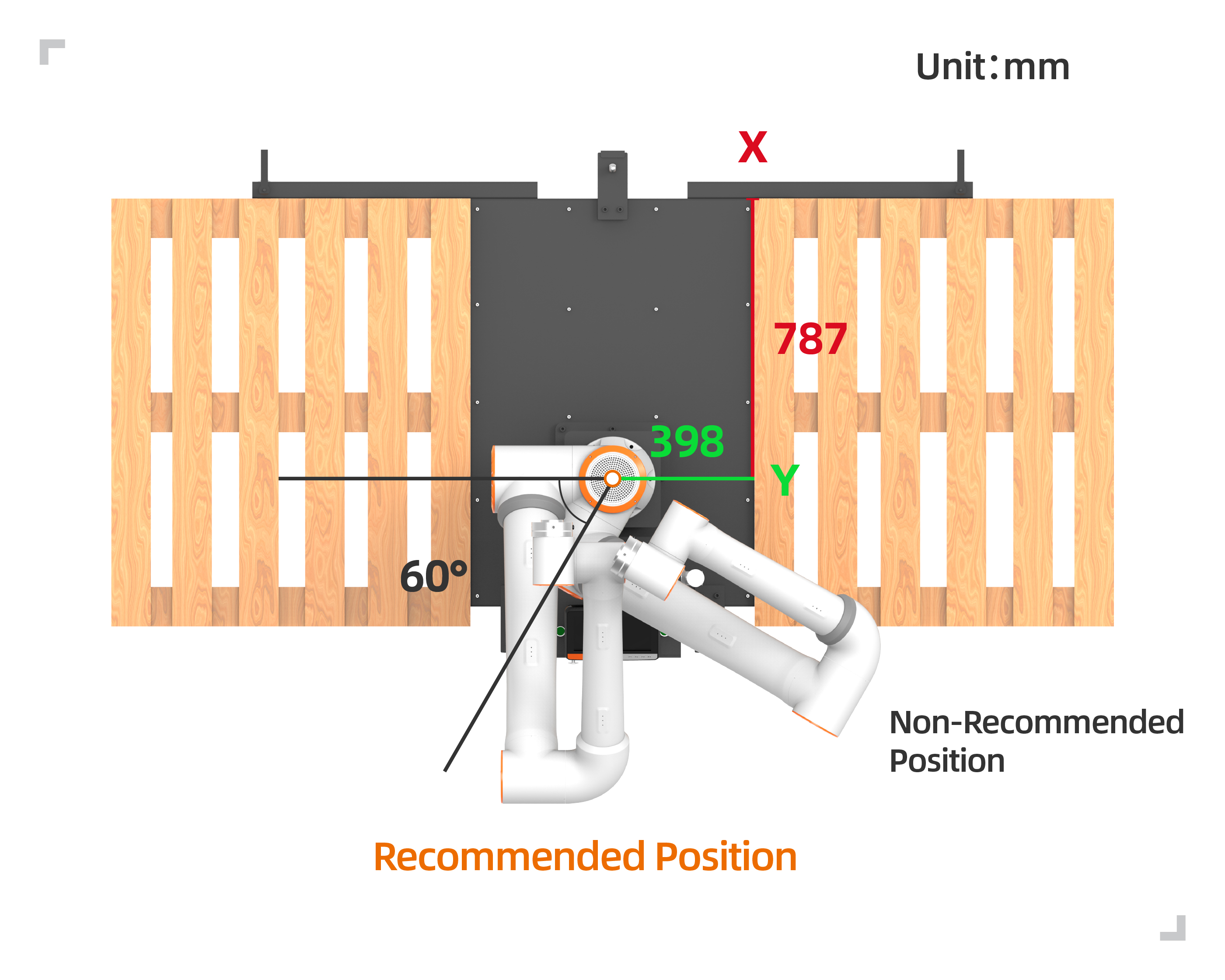
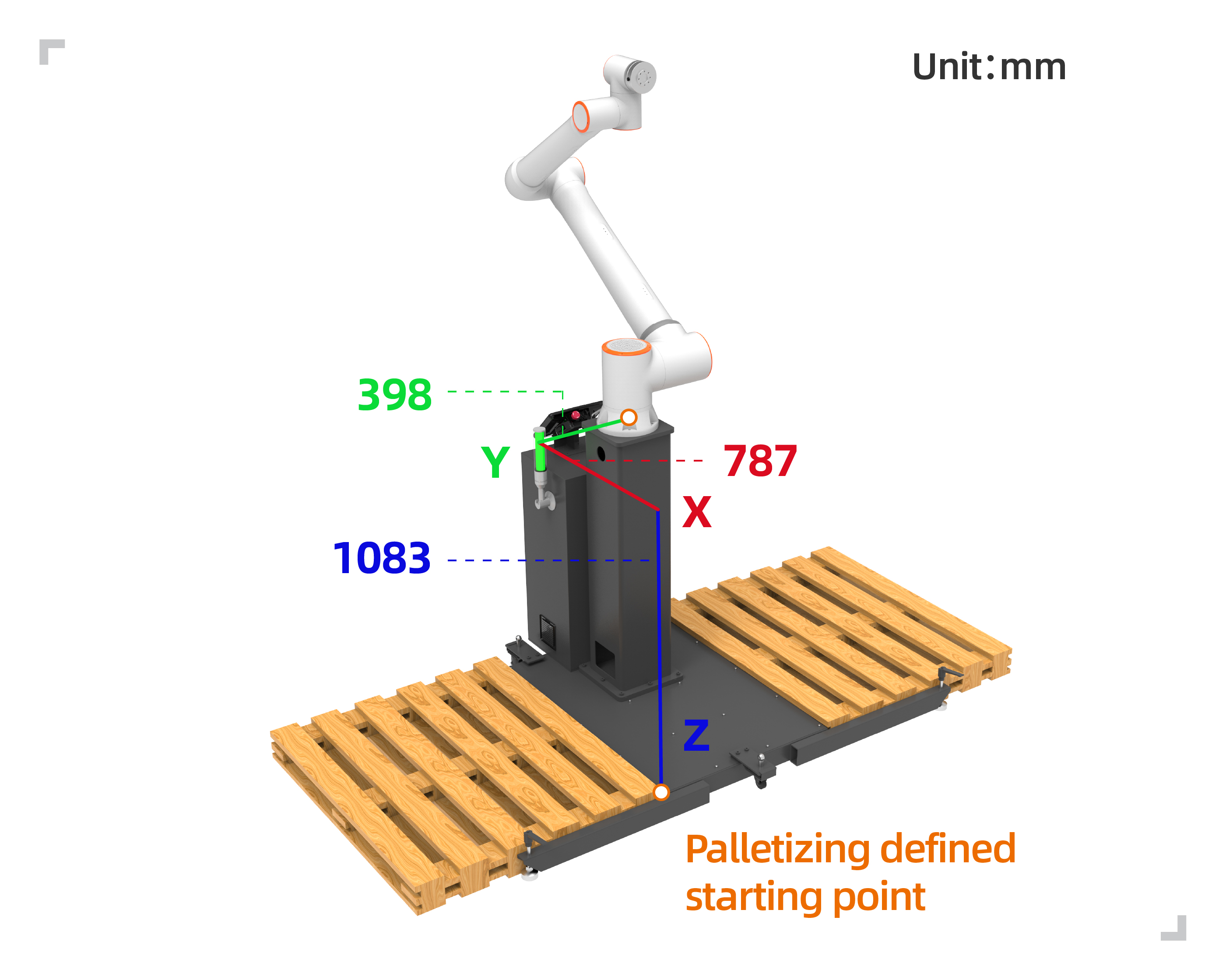
Figure 10-3-24 Palletizing Station
Important
X, Y, and Z are the absolute values of the coordinates of the point at the upper right corner of the left tray or the upper left corner of the right tray relative to the robot’s base coordinate system. Angle is the rotation angle during the robot’s installation, which is recommended to be 0 during installation.
Lifting height for picking up materials: User-defined lifting height after successfully picking up materials from the grabbing point.
Waiting time for picking up materials: The user can customize the waiting time for monitoring the negative pressure arrival signal after picking up materials, and repeat the picking up action when it is not in place.
First/second offset distance: User-defined offset distance for tilting the robot to the target point. (Note: The first offset parameter Z must be greater than the height of the box, otherwise it will collide with the already placed boxes during the stacking process).
Partition configuration: Click “Configuration” in the partition configuration column to enter the “Partition Configuration” pop-up window, set the partition size “length”, “width” and “height” and select the start and stop of the partition.
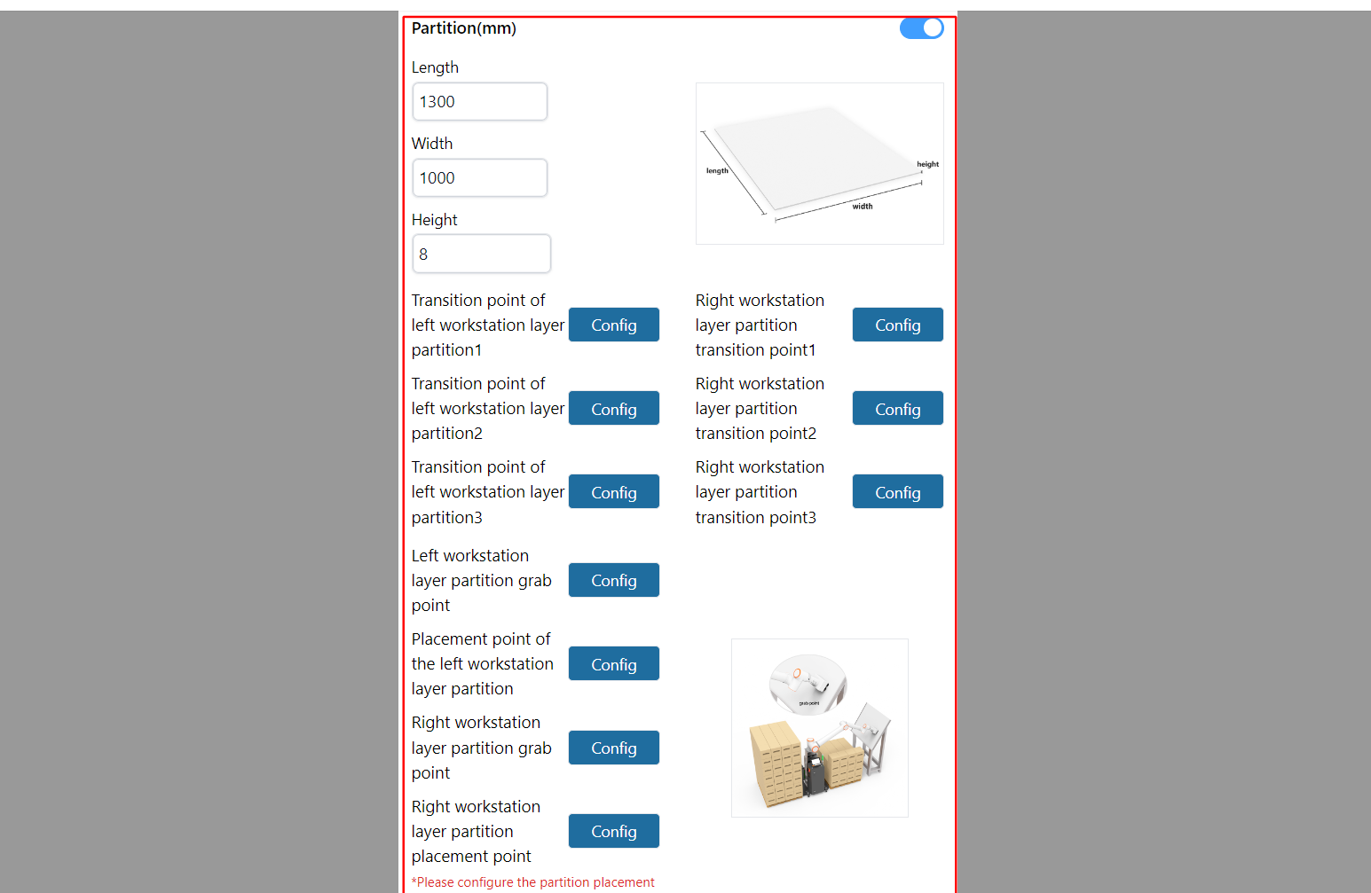
Figure 10-3-25 Partition configuration
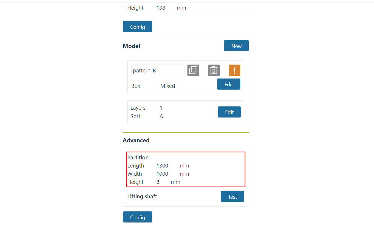
Figure 10-3-26 Recipe Management - Advanced Configuration Displays Partition Configuration
Then set the transition points of the partitions. There are three transition points for the partitions. The purpose of setting them is to roughly plan a movement path after grabbing the partitions to avoid collisions and being unable to complete the action of placing the partitions.
Note
Transition point 1 starts to move a certain distance from the box grab point and then teaches; transition point 2 starts to move a certain distance from transition point 1 and starts teaching, and can also become a transition intermediate point; transition point 3 starts to move from transition point 2 A distance is the last point before the partition is placed.
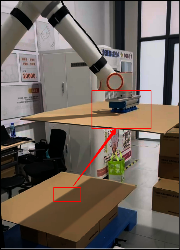
Figure 10-3-27 Partition transition point 1 (take the right station as an example)
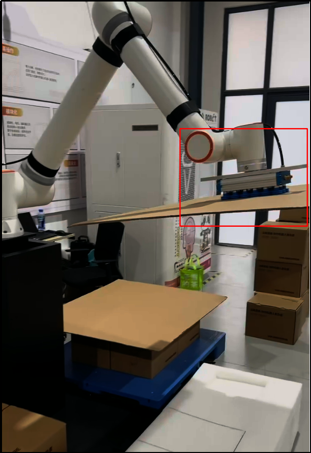
Figure 10-3-28 Partition transition point 2 (take the right station as an example)
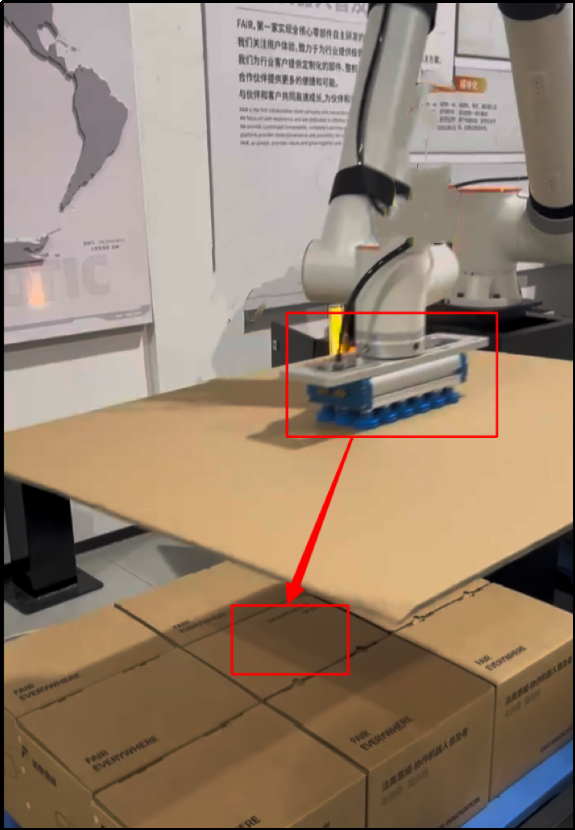
Figure 10-3-29 Partition transition point 3 (take the right station as an example)
Then set the grab point (keep the grab point at the center of the partition, and the bottom of the suction cup will be in a squeeze state when it contacts the partition) and placement point, and click “Confirm” to complete the partition information setting.
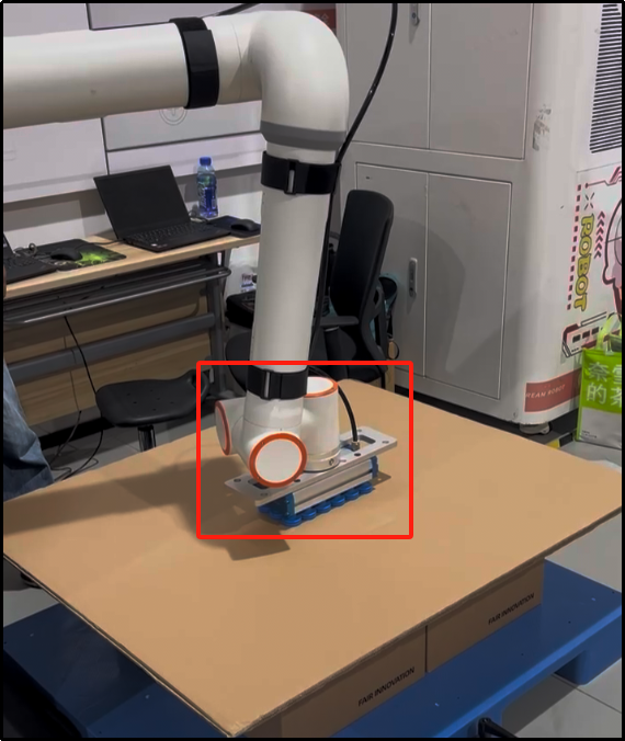
Figure 10-3-30 Partition grab point (take the right station as an example)
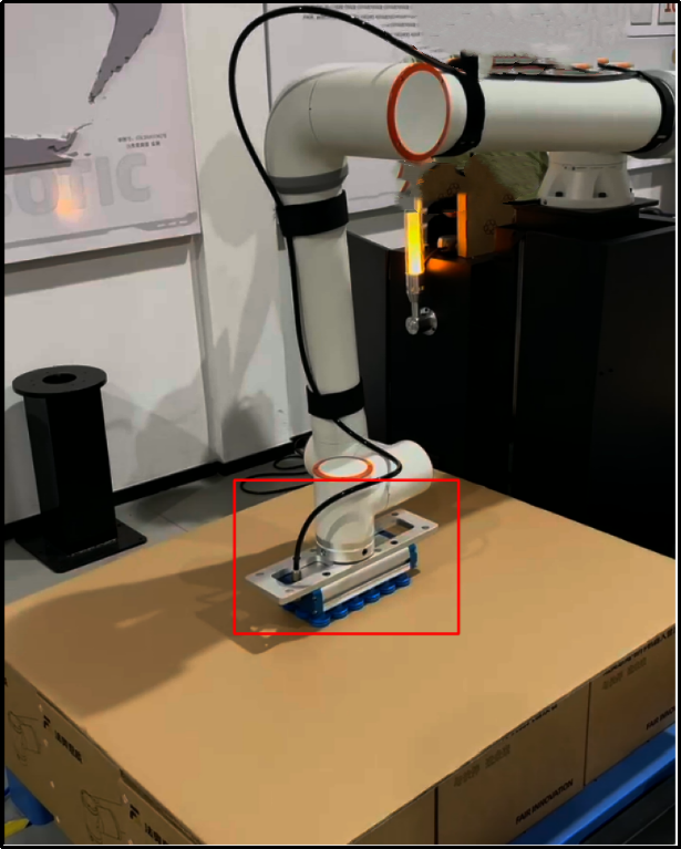
Figure 10-3-31 Partition placement point (take the right workstation as an example)
Lifting axis: Users can customize the start and stop of the lifting axis, communication parameters (IP address, port number and communication cycle), the floor number to start lifting and select the start and stop of the lifting axis.
Note
When the lifting shaft is working, the height it lifts each time is the height of the box.
When the lifting shaft function is turned on, the home page displays the advanced configuration content and displays the lifting shaft test button. Click the “Test” button to enter the “Lifting” button. Axis Test” pop-up window is used to test the accuracy of loading communication, rising and falling of the lifting axis to avoid problems such as inability to work and large errors when used directly.
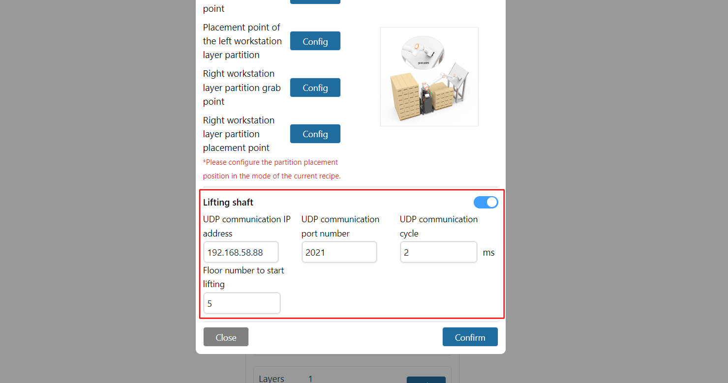
Figure 10-3-32 Lifting shaft configuration
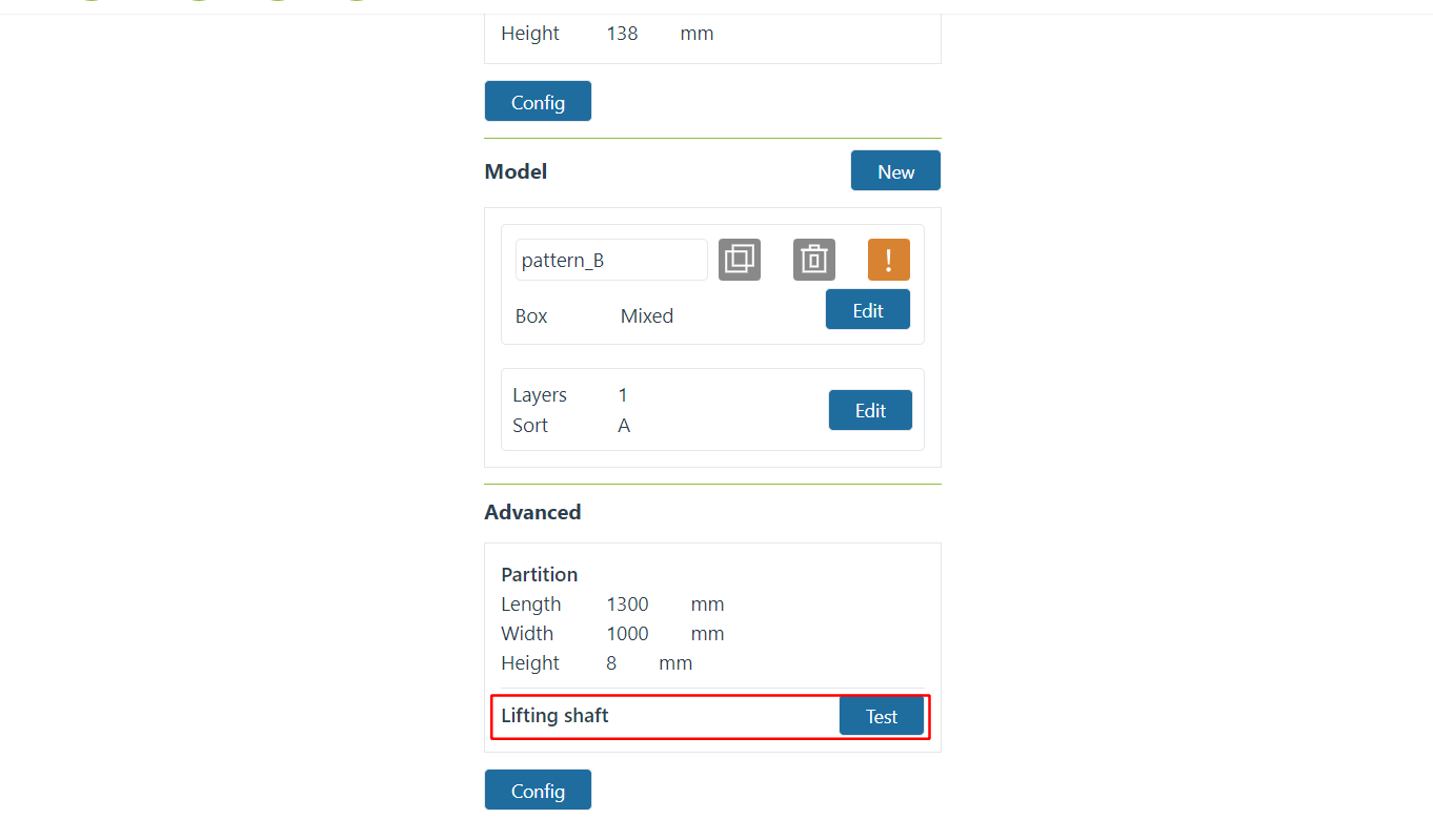
Figure 10-3-33 Recipe Management - Advanced Configuration Display Lifting Axis

Figure 10-3-34 Lifting shaft test
10.4. Program Generation
View “Program Generation” below the recipe display, and select the recipe based on the recipe and requirements. When recipes are selected for both left and right stations, startup priority needs to be selected; when a recipe is selected only for the left or right station, startup priority selection is not required. After entering the program name, click the “Generate” button.
Note
All program names start with “palletizing”. There is no need to input “palletizing”; just input the name after “_”. For example, for “palletizing_program”, input “program”.
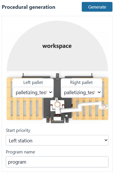
Figure 10-4-1 Program Generation – Selecting Recipes for Both Left and Right Stations
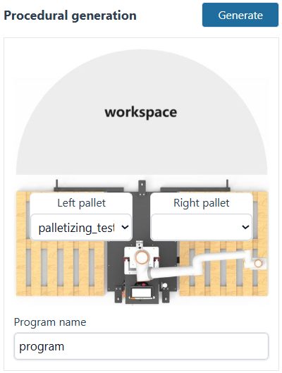
Figure 10-4-2 Program Generation – Selecting Recipe for Left Station, No Recipe for Right Station
Important
If no palletizing recipe is selected for the left or right station, it means that station is not enabled.
After successfully generating the program, be sure to manually save all subprograms and the main program in Program Teaching.
Depalletizing programs start with “de”. For example, if the palletizing program is “palletizing_program”, the depalletizing program would be “depalletizing_program”.
When running a program with recipes configured for both left and right stations, after simultaneously receiving the workpiece-in-position signals for left and right, work proceeds according to the set priority.
10.4.1. Single Pick Point Program
There are two scenarios for a single pick point program:
Left and right stations select the same recipe;
Left and right stations select different recipes, but the box pick point pose configured in the recipes is the same.
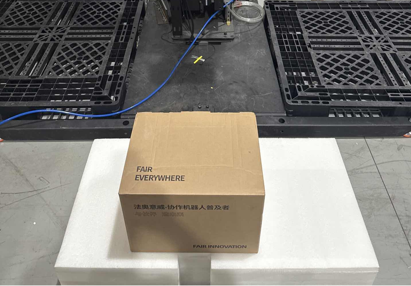
Figure 10-4-3 Single Pick Point Box Pick Point
10.4.2. Dual Pick Point Program
To configure a dual pick point program, the left and right stations must select different recipes, and the box pick point poses configured in the recipes must be different.

Figure 10-4-4 Dual Pick Point Box Pick Point