1. Introduction
fairino_hardware is an API interface developed based on ROS2 for FaAO collaborative robot, aiming at making it more convenient for entry-level users to use FaAO SDK. Through the parameter configuration file to configure the default parameters, it can adapt to different customer requirements.
2. fairino_hardware
This section explains how to configure the APP environment.
2.1. Basic Environment Installation
It is recommended to use Ubuntu22.04LTS(Jammy). Once the system is installed, you can install ROS2. Ros2-humble is recommended:https://docs.ros.org/en/humble/index.html。Before compiling fairino_hardware, you need to install the official ros2_control package. For ros2_control installation, see the tutorial:https://control.ros.org/humble/index.html。There are two official ros2_control installation modes, namely command installation mode and source code compilation installation mode. Because command installation mode may lead to incomplete installation of function package, it is recommended to use source code compilation installation mode.
The detail progress of installation of ROS2(humble):
1.Open a shell window,set locale information
1locale  # check for UTF-8
2
3sudo apt update && sudo apt install locales
4sudo locale-gen en_US en_US.UTF-8
5sudo update-locale LC_ALL=en_US.UTF-8 LANG=en_US.UTF-8
6export LANG=en_US.UTF-8
7
8locale  # verify settings
2.Set source
1sudo apt install software-properties-common
2sudo add-apt-repository universe
3
4sudo apt update && sudo apt install curl -y
5sudo curl -sSL https://raw.githubusercontent.com/ros/rosdistro/master/ros.key -o /usr/share/keyrings/ros-archive-keyring.gpg
6
7echo "deb [arch=$(dpkg --print-architecture) signed-by=/usr/share/keyrings/ros-archive-keyring.gpg] http://packages.ros.org/ros2/ubuntu $(. /etc/os-release && echo $UBUNTU_CODENAME) main" | sudo tee /etc/apt/sources.list.d/ros2.list > /dev/null
3.Install ROS2
1sudo apt update
2sudo apt upgrade
3sudo apt install ros-humble-desktop
4.Then install dev-tool
1sudo apt install ros-dev-tools
The detail installation process of ros2_control:
1.First the ROS2 source must be added
1source /opt/ros/humble/setup.bash
2.Create ros2_control workspace, download the source code
1mkdir -p ~/ros2_control_ws/src
2cd ~/ros2_control_ws/
3wget https://raw.githubusercontent.com/ros-controls/ros2_control_ci/master/ros_controls.$ROS_DISTRO.repos
4vcs import src < ros_controls.$ROS_DISTRO.repos
3.Install dependences
1rosdep update --rosdistro=$ROS_DISTRO
2sudo apt-get update
3rosdep install --from-paths src --ignore-src -r -y
4.Build ros2_control
1. /opt/ros/${ROS_DISTRO}/setup.sh
2colcon build --symlink-install
2.2. Compile and build fairino_hardware
1. Create the colcon workspace fairino_hardware consists of two packages: fairino_msgs for custom data structures and fairino_hardware for the program body. Once you have the base environment installed, create a colcon workspace, like this:
Rmenber source ROS2&ros2_control first
1source /opt/ros/humble/setup.bash
2source ~/ros2_control_ws/install/setup.bash
1cd ~/
2mkdir -p ros2_ws/src
2. Compile feature packs Copy the package code to ros2_ws/src and run the following command inside ros2_ws:
1colcon build --packages-select fairino_msgs
Wait for the previous command to finish compiling, then start to build fairino_hardware package:
1colcon build --packages-select fairino_hardware
3. Quick start
3.1. Starting the process
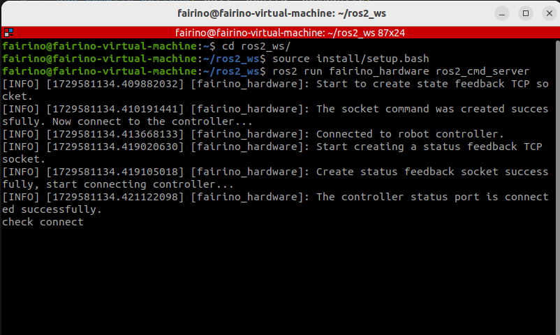
On Ubuntu, open the command line and type:
1cd ros2_ws
2source install/setup.bash
3ros2 run fairino_hardware ros2_cmd_server
3.2. View the manipulator state feedback process
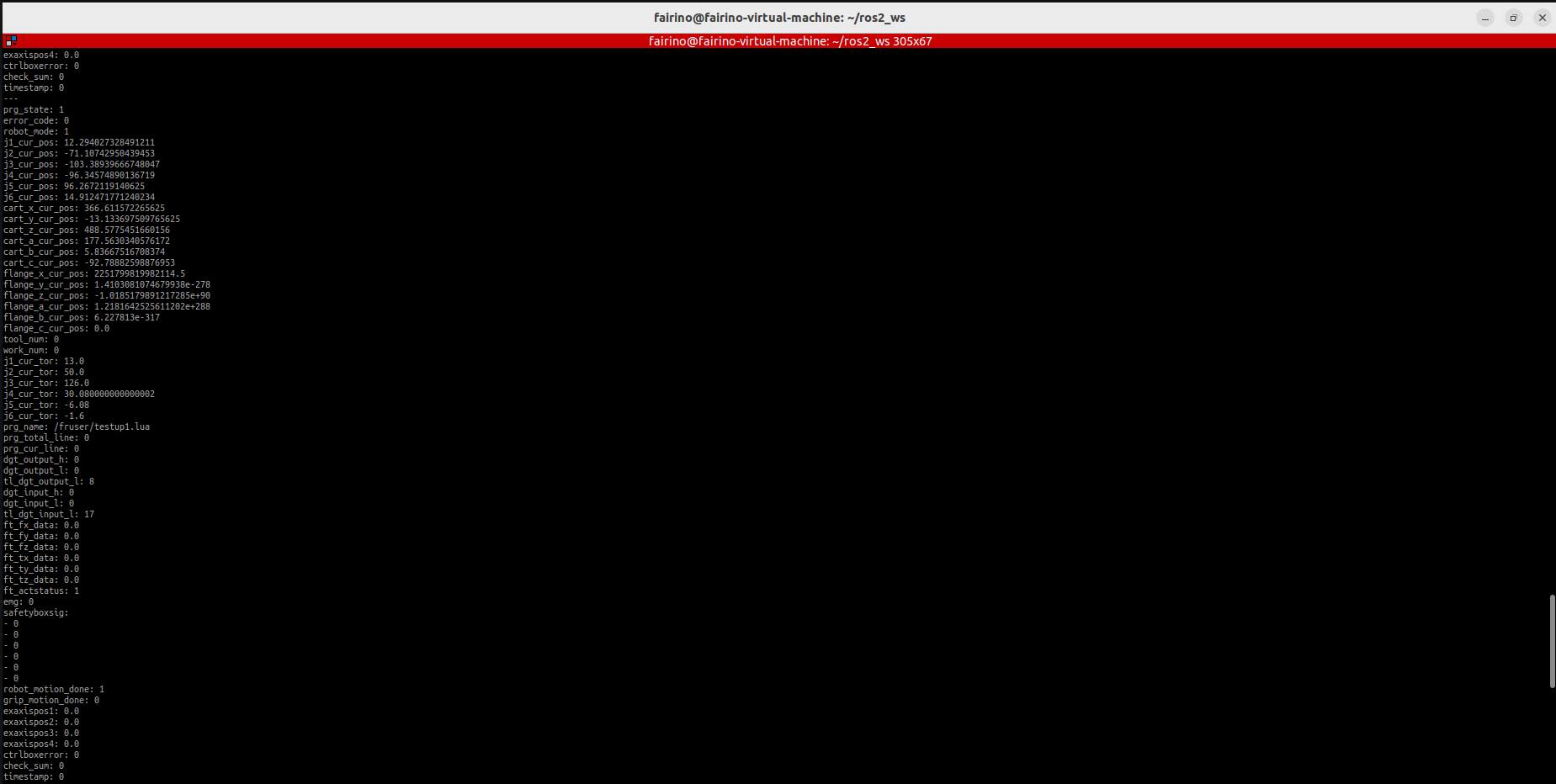
The state feedback of the manipulator is published through the topic. Users can observe the state data refresh through the commands that come with ros2, or write programs to obtain the data.
On ubuntu, open the command line and type:
1cd ros2_ws
2source install/setup.bash
3ros2 topic echo /nonrt_state_data
Can see the status data being refreshed in the command-line window, as shown in the following screenshot:
3.3. Process for issuing instructions
On ubuntu, open the command line and type:
1cd ros2_ws
2source install/setup.bash
3rqt
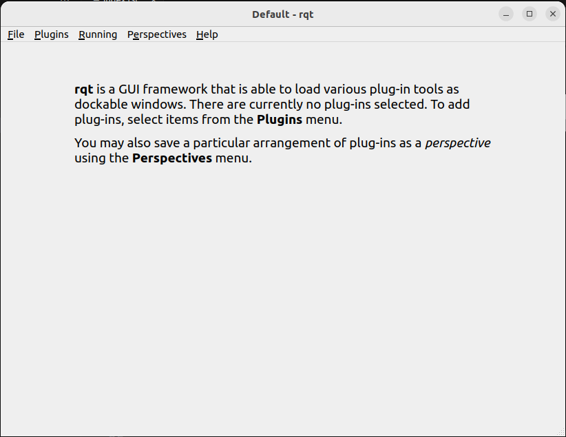
After executing the above command, an rqt GUI will be brought up, as shown in the following figure.
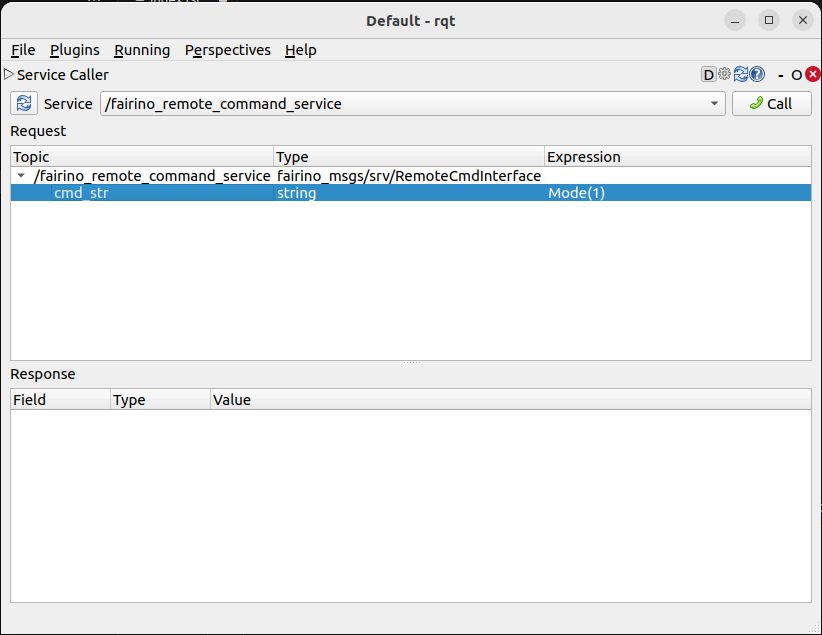
In the GUI, select plugins->serivce->serivce caller, bring up the following screen, select /fairino_remote_command_service, Enter the instruction string in the interface expression and click call to see the reply message pop up in the dialog box below.
Important
Input string rule description:
The program internally filters the input strings to be of the form [function name](), and the parenthesis argument string must consist of letters, numbers, commas, and minus signs; any other characters or Spaces will throw an error.
Instruction feedback value description:
Except for the GET command, which returns a string, the rest of the function feedback values are int values, typically 0 for error, 1 for correct execution, and any other values refer to the error code defined in the xmlrpc SDK.
3.4. Modifying the parameter flow
Since the simplified SDK is to improve the native SDK interface, it can be simplified because some parameters are given default values. However, in the actual use process, the default parameters can not meet the requirements, in this case, you can modify the value of the corresponding default parameters and then load them into the node.
There is a fairino_remotecmdinterface_para.yaml parameter file in the source code file. The parameters in the file are preset default parameters, which are used to simplify the instruction input parameters. You can modify the parameters according to your specific needs, and then use the command to modify the parameters dynamically: ros2 param load fr_command_server ~/ros2_ws/src/fairino_hardware/fairino_remotecmdinterface_para.yaml。
4. API Description
  1/*
  2Function description: Store a joint point position information
  3id - Stores the point id, starting with 1, independently of the point id of CARTPoint
  4double j1−j6 − 6 joint positions in degrees
  5*/
  6int JNTPoint(int id, double j1, double j2, double j3, double j4, double j5, double j6)
  7// Examples
  8JNTPoint(1,10,11,12,13,14,15)
  9
 10/*
 11Function description: Store a Cartesian point position information
 12id - Stores the point id, starting from 1, independently of the point id of JNTPoint
 13double x,y,z,rx,ry,yz - Cartesian point position information, position in mm, Angle in degrees
 14*/
 15int CARTPoint(int id, double x,y,z,rx,ry,rz)//Store a point in Cartesian space
 16// Examples
 17CARTPoint(1,100,110,200,0,0,0)
 18
 19/*
 20Function description: Get the joint or Cartesian position information of the specified sequence point
 21string name - 'JNT' or 'CART', where JNT stands for getting information about joint points and 'CART' stands for getting information about Cartesian points
 22int id - The point id, starting at 1
 23*/
 24string GET(string name, int id)//Get the contents of the corresponding id sequence number point; name can be entered as JNT or CART
 25// Examples
 26GET(JNT,1)
 27
 28/*
 29Function description: Drag mode switch
 30uint8_t state - 1- Enable drag mode,0- disable drag mode
 31*/
 32int DragTeachSwitch(uint8_t state)
 33// Examples
 34DragTeachSwitch(0)
 35
 36/*
 37Function description: Manipulator enable switch
 38uint8_t state - 1 -manipulator enabled,0 -manipulator deenabled
 39*/
 40int RobotEnable(uint8_t state)
 41// Examples
 42RobotEnable(1)
 43
 44/*
 45Function description:Mode switching
 46uint8_t state - 1- Manual mode,0- automatic mode
 47*/
 48int Mode(uint8_t state)
 49// Examples
 50Mode(1)
 51
 52/*
 53Function description:Set the manipulator speed in the current mode
 54float vel - Percentage of speed, ranging from 1-100
 55*/
 56int SetSpeed(float vel)
 57// Examples
 58SetSpeed(10)
 59
 60/*
 61Function description:Sets and loads the tool coordinate system with the specified sequence number
 62int id - Tool coordinate system number, range 1-15
 63float x,y,z,rx,ry,rz - Offset information for the tool coordinate system
 64*/
 65int SetToolCoord(int id, float x,float y, float z,float rx,float ry,float rz)
 66// Examples
 67SetToolCoord(1,0,0,0,0,0,0)
 68
 69/*
 70Function description:Set the list of tool coordinate systems
 71int id - Tool coordinate system number, range 1-15
 72float x,y,z,rx,ry,rz - Offset information for the tool coordinate system
 73*/
 74int SetToolList(int id, float x,float y, float z,float rx,float ry,float rz );
 75// Examples
 76SetToolList(1,0,0,0,0,0,0)
 77
 78/*
 79Function description:Set the external tool coordinate system
 80int id - Tool coordinate system number, range 1-15
 81float x,y,z,rx,ry,rz - Offset information for the external tool coordinate system
 82*/
 83int SetExToolCoord(int id, float x,float y, float z,float rx,float ry,float rz);
 84// Examples
 85SetExToolCoord(1,0,0,0,0,0,0)
 86
 87/*
 88Function description:Sets the list of external tool coordinate systems
 89int id - Tool coordinate system number, range 1-15
 90float x,y,z,rx,ry,rz - Offset information for the external tool coordinate system
 91*/
 92int SetExToolList(int id, float x,float y, float z,float rx,float ry,float rz);
 93// Examples
 94SetExToolList(1,0,0,0,0,0,0)
 95
 96/*
 97Function description:Set the workpiece coordinate system
 98int id - Workpiece coordinate system number, range 1-15
 99float x,y,z,rx,ry,rz - Offset information of the workpiece coordinate system
100*/
101int SetWObjCoord(int id, float x,float y, float z,float rx,float ry,float rz);
102// Examples
103SetWObjCoord(1,0,0,0,0,0,0)
104
105/*
106Function description:Set the list of workpiece coordinate systems
107int id - Workpiece coordinate system number, range 1-15
108float x,y,z,rx,ry,rz - Offset information of the workpiece coordinate system
109*/
110int SetWObjList(int id, float x,float y, float z,float rx,float ry,float rz);
111// Examples
112SetWObjList(1,0,0,0,0,0,0)
113
114/*
115Function description:Set the end load weight
116float weight - Load weight in kg
117*/
118int SetLoadWeight(float weight);
119// Examples
120SetLoadWeight(3.5)
121
122/*
123Function description:Set the end-load centroid coordinates
124float x,y,z - Coordinates of the center of mass in mm
125*/
126int SetLoadCoord(float x,float y,float z);
127// Examples
128SetLoadCoord(10,20,30)
129
130/*
131Function description:Set the robot installation mode
132uint8_t install - Installation mode,0- formal,1- side,2- inverted
133*/
134int SetRobotInstallPos(uint8_t install);
135// Examples
136SetRobotInstallPos(0)
137
138/*
139Function description:Set the robot installation Angle, free installation
140double yangle - Angle of inclination
141double zangle - Angle of rotation
142*/
143int SetRobotInstallAngle(double yangle,double zangle);
144// Examples
145SetRobotInstallAngle(90,0)
146
147
148//Security configuration
149/*
150Function description:Set the robot collision level
151float level1-level6 - Collision levels for axes 1-6, ranging from 1-10
152*/
153int SetAnticollision(float level1, float level2, float level3, float level4, float level5, folat level6);
154// Examples
155SetAnticollision(1,1,1,1,1,1)
156
157/*
158     * @brief  Set the post-collision strategy
159     * @param  [in] strategy  0-Error and stop, 1-Continue running
160     * @param  [in] safeTime  Safe stop time [1000 - 2000] ms
161     * @param  [in] safeDistance  Safe stop distance [1-150] mm
162     * @param  [in] safeVel  Safe speed [50-250] mm/s
163     * @param  [in] safetyMargin  Safety factor for J1-J6 [1-10]
164     * @return  Error code
165*/
166    int SetCollisionStrategy(int strategy, int safeTime, int safeDistance, int safeVel, int safetyMargin[]);
167// Example
168SetCollisionStrategy(1);
169
170/**
171* @brief sets the collision detection method of the robot
172* @param [in] method Collision detection method: 0- current mode; 1- Dual encoder; 2- Current and dual encoder turn on simultaneously
173* @param [in] thresholdMode Collision level threshold method 0-Collision level fixed threshold mode 1- Customize collision detection thresholds
174* @return  error code
175*/
176int SetCollisionDetectionMethod(int method, int thresholdMode);
177// Examples
178SetCollisionDetectionMethod(0,0)
179
180/**
181* @brief Indicates that collision detection is disabled in static mode
182* @param [in] status 0- Off; 1- Open
183* @return  error code
184*/
185int SetStaticCollisionOnOff(int status);
186// Examples
187SetStaticCollisionOnOff(1)
188
189/**
190    * @brief joint torque power detection
191    * @param [in] status 0- Off; 1- Open
192    * @param [in] power Set maximum power (W);
193* @return  error code
194*/
195    int SetPowerLimit(int status, double power);
196//Examples
197SetPowerLimit(1,100)
198
199    /**
200*@brief  Configured force sensor
201*@param  [in] company  Manufacturer of force sensors, 17-KUNWEI,19-CAAA,20-ATI,21-HKM,22-GZCX,23-NBIT,24-XJC,26-NSR
202*@param  [in] device  Device number,  KUNWEI(0-KWR75B),CAAA(0-MCS6A-200-4),ATI(0-AXIA80-M8),HKM(0-MST2010),GZCX(0-WHC6L-YB-10A),NBIT(0-XLH93003ACS),XJC(0-XJC-6F-D82),NSR(0-NSR-FTSensorA)
203*@param  [in] softvesion  Software version. The value is not used. The default value is 0
204*@param  [in] bus The device is attached to the terminal bus and is not in use. The default value is 0
205*@return  Error code
206     */
207    int FT_SetConfig(int company, int device, int softvesion, int bus);
208// Examples
209FT_SetConfig(0,1,0,0)
210
211    /**
212*@brief  Get the force sensor configuration
213*@param  [in] company  Force sensor manufacturer, to be determined
214*@param  [in] device  Device number, not used yet. The default value is 0
215*@param  [in] softvesion  Software version. The value is not used. The default value is 0
216*@param  [in] bus The device is attached to the terminal bus and is not in use. The default value is 0
217*@return  Error code
218     */
219    int FT_GetConfig(int *company, int *device, int *softvesion, int *bus);
220// Examples
221FT_GetConfig()
222
223    /**
224*@brief  Force sensor activation
225*@param  [in] act  0- reset, 1- activate
226*@return  Error code
227     */
228    int FT_Activate(uint8_t act);
229// Examples
230FT_Activate(1)
231
232    /**
233*@brief  Force sensor calibration
234*@param  [in] act  0- zero removal, 1- zero correction
235*@return  Error code
236     */
237    int  FT_SetZero(uint8_t act);
238// Examples
239FT_SetZero(1)
240
241    /**
242*@brief  Collision guard
243*@param  [in] flag 0- Disable collision guard. 1- Enable collision guard
244*@param  [in] sensor_id Force sensor number
245*@param  [in] select  Select the six degrees of freedom whether to detect collision, 0- no detection, 1- detection
246*@param  [in] ft  Impact force/torque,fx,fy,fz,tx,ty,tz
247*@param  [in] max_threshold Maximum threshold
248*@param  [in] min_threshold Minimum threshold
249*@note   Force/torque detection range:(ft-min_threshold, ft+max_threshold)
250*@return  Error code
251     */
252    int FT_Guard(uint8_t flag, int sensor_id, uint8_t select[6], ForceTorque *ft, float max_threshold[6], float min_threshold[6]);
253// Examples
254FT_Guard(1,1,0,0,1,0,0,0,0,0,100,0,0,0,0,0,200,0,0,0,0,0,50,0,0,0)
255
256
257    /**
258*@brief  Constant force control
259*@param  [in] flag 0- turn off constant force control, 1- turn on constant force control
260*@param  [in] sensor_id Force sensor number
261*@param  [in] select  Select the six degrees of freedom whether to detect collision, 0- no detection, 1- detection
262*@param  [in] ft  Impact force/torque,fx,fy,fz,tx,ty,tz
263*@param  [in] ft_pid Force pid parameter, torque pid parameter
264*@param  [in] adj_sign Adaptive start-stop control, 0- off, 1- on
265*@param  [in] ILC_sign ILC start stop control, 0- stop, 1- training, 2- operation
266*@param  [in] Maximum Adjustment distance, unit: mm
267*@param  [in] Maximum Adjustment Angle, unit: deg
268*@return  Error code
269     */
270    int FT_Control(uint8_t flag, int sensor_id, uint8_t select[6], ForceTorque *ft, float ft_pid[6], uint8_t adj_sign, uint8_t ILC_sign, float max_dis, float max_ang, int filter_Sign = 0, int posAdapt_sign = 0, int isNoBlock = 0);
271// Examples
272FT_Control(1,1,0,0,1,0,0,0,0,0,-10,0,0,0,0.0005,0,0,0,0,0,0,0,100,10,0,0,0)
273
274
275    /**
276*@brief  Compliant control on
277*@param  [in] p Coefficient of position adjustment or compliance
278*@param  [in] force Compliant opening force threshold, unit: N
279*@return  Error code
280     */
281    int FT_ComplianceStart(float p, float force);
282// Examples
283FT_ComplianceStart(0.005,20)
284
285    /**
286*@brief  Compliant control off
287*@return  Error code
288     */
289    int  FT_ComplianceStop();
290// Examples
291FT_ComplianceStop()
292
293
294/*
295Function description:Set the positive limit, note that the set value must be within the hard limit range
296float limit1-limit6 - Six joint limit values
297*/
298int SetLimitPositive(float limit1, float limit2, float limit3, float limit4, float limit5, float limit6);
299// Examples
300SetLimitPositve(100,90,90,90,90,90)
301
302/*
303Function description:Set the negative limit, note that the set value must be within the hard limit range
304float limit1-limit6 - Six joint limit values
305*/
306int SetLimitNegative(float limit1, float limit2, float limit3, float limit4, float limit5, float limit6);
307// Examples
308SetLimitNegative(-100,-90,-90,-90,-90,-90)
309
310/*
311Function description:Error state removal
312*/
313int ResetAllError();
314
315/*
316Function description:Joint friction compensation switch
317uint8_t state - 0- off, 1- on
318*/
319int FrictionCompensationOnOff(uint8_t state);
320// Examples
321FrictionCompensationOnOff(1)
322
323/*
324Function description:Set the joint friction compensation coefficient -formal suit
325float coeff1-coeff6 - Six joint compensation coefficients, ranging from 0-1
326*/
327int SetFrictionValue_level(float coeff1,float coeff1,float coeff3,float coeff4,float coeff5,float coeff6);
328// Examples
329SetFrictionValue_level(1,1,1,1,1,1)
330
331/*
332Function description:Set the joint friction compensation coefficient -side loading
333float coeff1-coeff6 - Six joint compensation coefficients, ranging from 0-1
334*/
335int SetFrictionValue_wall(float coeff1,float coeff1,float coeff3,float coeff4,float coeff5,float coeff6);
336// Examples
337SetFrictionValue_wall(0.5,0.5,0.5,0.5,0.5,0.5)
338
339/*
340Function description:Set the joint friction compensation coefficient -flip
341float coeff1-coeff6 - Six joint compensation coefficients, ranging from 0-1
342*/
343int SetFrictionValue_ceiling(float coeff1,float coeff1,float coeff3,float coeff4,float coeff5,float coeff6);
344// Examples
345SetFrictionValue_ceiling(0.5,0.5,0.5,0.5,0.5,0.5)
346
347
348//Peripheral device control
349/*
350Function description:Activated gripper
351int index - Clamp claw number
352uint8_t act - 0- Reset, 1- Activate
353*/
354int ActGripper(int index,uint8_t act);
355// Examples
356ActGripper(1,1)
357
358/*
359Function description:Control gripper
360int index - Clamp claw number
361int pos - Percentage of position, range 0-100
362*/
363int MoveGripper(int index,int pos);
364// Examples
365MoveGripper(1,10)
366
367
368//IO控制
369/*
370Function description:Set the control box digital output
371int id - io number, range 0-15
372uint_t status - 0- off, 1- on
373*/
374int SetDO(int id,uint8_t status);
375// Examples
376SetDO(1,1)
377
378/*
379Function description:Set tool number output
380int id - io number, range 0-1
381uint_t status - 0- off, 1- on
382*/
383int SetToolDO(int id,uint8_t status);
384// Examples
385SetToolDO(0,1)
386
387/*
388Function description:Set the control box analog output
389int id - io number, range 0-1
390float vlaue - Percentage of current or voltage value, range 0-100
391*/
392int SetAO(int id,float value);
393// Examples
394SetAO(1,100)
395
396/*
397Function description:Set tool analog output
398int id - io number, range 0
399float vlaue - Percentage of current or voltage value, range 0-100
400*/
401int SetToolAO(int id,float value);
402// Examples
403SetToolAO(0,100)
404
405
406//Motor command
407/*
408Function description:Robot JOG Start
409uint8_t ref - 0-joint JOG, 2-JOG in base coordinate system, 4-JOG in tool coordinate system, 8-JOG in workpiece  coordinate system
410uint8_t nb - 1 - Joint 1 (or X-axis), 2 - Joint 2 (or Y-axis), 3 - Joint 3 (or Z-axis), 4 - Joint 4 (or Rotation around X-axis), 5 - Joint 5 (or Rotation around Y-axis), 6 - Joint 6 (or Rotation around Z-axis)
411uint8_t dir - 0- negative direction, 1- positive direction
412float vel - Percentage of speed, ranging from 0-100
413*/
414int StartJOG(uint8_t ref, uin8_t nb, uint8_t dir, float vel);
415// Examples
416StartJOG(1,1,1,10)
417
418/*
419Function description:Robot JOG Stop
420uint8_t ref - 0 - Joint Jog Stop, 2 - Jog Stop in Base Coordinate System, 4 - Jog Stop in Tool Coordinate System, 8 - Jog Stop in Workpiece Coordinate System
421*/
422int StopJOG(uint8_t ref);
423// Examples
424StopJOG(1)
425
426/*
427Function description:Robot JOG Immediate Stop
428*/
429int ImmStopJOG();
430
431/*
432Function description:Joint space motion
433string point_name - For example, JNT1 is the point with the sequence number 1 of the node information,CART1 is the point with the sequence number 1 of the Cartesian point information,MoveJ instruction supports the input of the node or Cartesian point. It should be noted that because the default parameters of the MoveJ instruction specify the tool coordinate system and the workpiece coordinate system, when the serial number of the two coordinate systems is inconsistent with the current load, the instruction will cause an error. It is necessary to modify the coordinate system parameters and LOAD parameters in the default parameters before running the movement instruction.
434float vel - Command speed percentage, range 0-100
435int tool - tool coordinate index
436int user - reference coordinate index
437*/
438int MoveJ(string point_name, float vel,int tool, int user);//point_name indicates the input prestored point information,
439// Examples
440MoveJ(JNT1,10,1,1)
441
442/*
443Function description:Rectilinear motion in Cartesian space
444string point_name - For example, JNT1 is the point whose sequence number is 1,CART1 is the point whose sequence number is 1, and the MoveL instruction supports the input of the point or Cartesian point. It should be noted that since the default parameters of the MoveL instruction specify the tool coordinate system and the workpiece coordinate system, when the serial number of the two coordinate systems is inconsistent with the current load, the instruction will cause an error. The coordinate system parameters and load parameters need to be modified in the default parameters before running the motion instruction.
445float vel - Command speed percentage, range 0-100
446*/
447int MoveL(string point_name,float vel);
448// Examples
449MoveL(CART1,10)
450
451/*
452Function description:Circular motion in Cartesian space
453string point1_name point2_name - For example, JNT1 is the point whose sequence number is 1,CART1 is the point whose sequence number is 1. MoveC command supports the input of the point or Cartesian point, but the two points must be of the same type, that is, the first point does not support the input of the joint space point and the second point input of the Cartesian point. It should be noted that because the default parameters of the MoveC instruction specify the tool coordinate system and the workpiece coordinate system, when the serial number of the two coordinate systems is inconsistent with the current load, the instruction will cause an error. It is necessary to modify the coordinate system parameters and LOAD parameters in the default parameters before running the movement instruction.
454float vel - Command speed percentage, range 0-100
455*/
456int MoveC(string point1_name,string point2_name, float vel);
457// Examples
458MoveC(JNT1,JNT2,10)
459
460/*
461Function description:The spline movement begins
462*/
463int SplineStart();
464
465/*
466Function description:Joint space spline movement, this command only supports the input of joint data such as JNT1, the input of Cartesian point will report an error
467string point_name - The prestored point name, such as JNT1, is the point whose sequence number is 1.
468float vel - Percentage of speed, range 0-100
469*/
470int SplinePTP(string point_name, float vel);
471// Examples
472SplinePTP(JNT2,10)
473
474/*
475Function description:The spline movement is over
476*/
477int SplineEnd();
478
479/*
480Function description:The Cartesian space spline motion begins
481uint8_t ctlpoint - 0- trajectory passes through the path point, 1- trajectory does not pass through the control point, at least 4 points
482*/
483int NewSplineStart(uint8_t ctlpoint);
484// Examples
485NewSplineStrart(1)
486
487/*
488Function description:For Cartesian space spline movement, only Cartesian space points such as CART1 can be entered, and an error will be reported when entering joint space points
489string point_name - Prestored point names, such as CART1, are points in Cartesian space with sequence number 1.
490float vel - Percentage of speed, range 0-100
491int lastflag - 0- not the last point, 1- the last point
492*/
493int NewSplinePoint(string point_name, float vel, int lastflag);
494// Examples
495NewSplinePoint(JNT2,20,0)
496
497/*
498Function description:The Cartesian space spline motion ends
499*/
500int NewSplineEnd();
501
502/*
503Function description:Stop motion
504*/
505int StopMotion();
506
507/*
508Function description:Global shift of point position begins
509int flag - 0- Offset in base coordinate/workpiece coordinate, 2- offset in tool coordinate
510double x,y,z,rx,ry,rz - Offset pose amount
511*/
512int PointsOffsetEnable(int flag,double x,double y,double z,double rx,double ry,double rz);
513// Examples
514PointsOffsetEnable(1,10,10,10,0,0,0)
515
516/*
517Function description:The point offset is complete
518*/
519int PointsOffsetDisable();